BL18 Screw Fastening Machine Troubleshooting: 53 Fast Fixes

53 BL18 screw fastening machine troubleshooting answers, each linked to the exact minute of the official JHIMS training video that fixes it.
Troubleshooting FAQ

BL18 Screw Fastening Machine Troubleshooting: 53 Fast Fixes

Every one of the 53 questions below is answered twice: a fix you can read in 20 seconds, and the exact minute of the official JHIMS training video where an engineer performs that fix on a real BL18.

How to Use This Page

Every answer below gives you a short written fix and the exact minute of the official JHIMS training video where an engineer performs that fix on a real BL18. Use this screw fastening machine troubleshooting index before you open a service ticket: most BL18 faults are cleared in under ten minutes with the video below. Use the 60-second triage first, then open the symptom group that matches what the machine is doing.

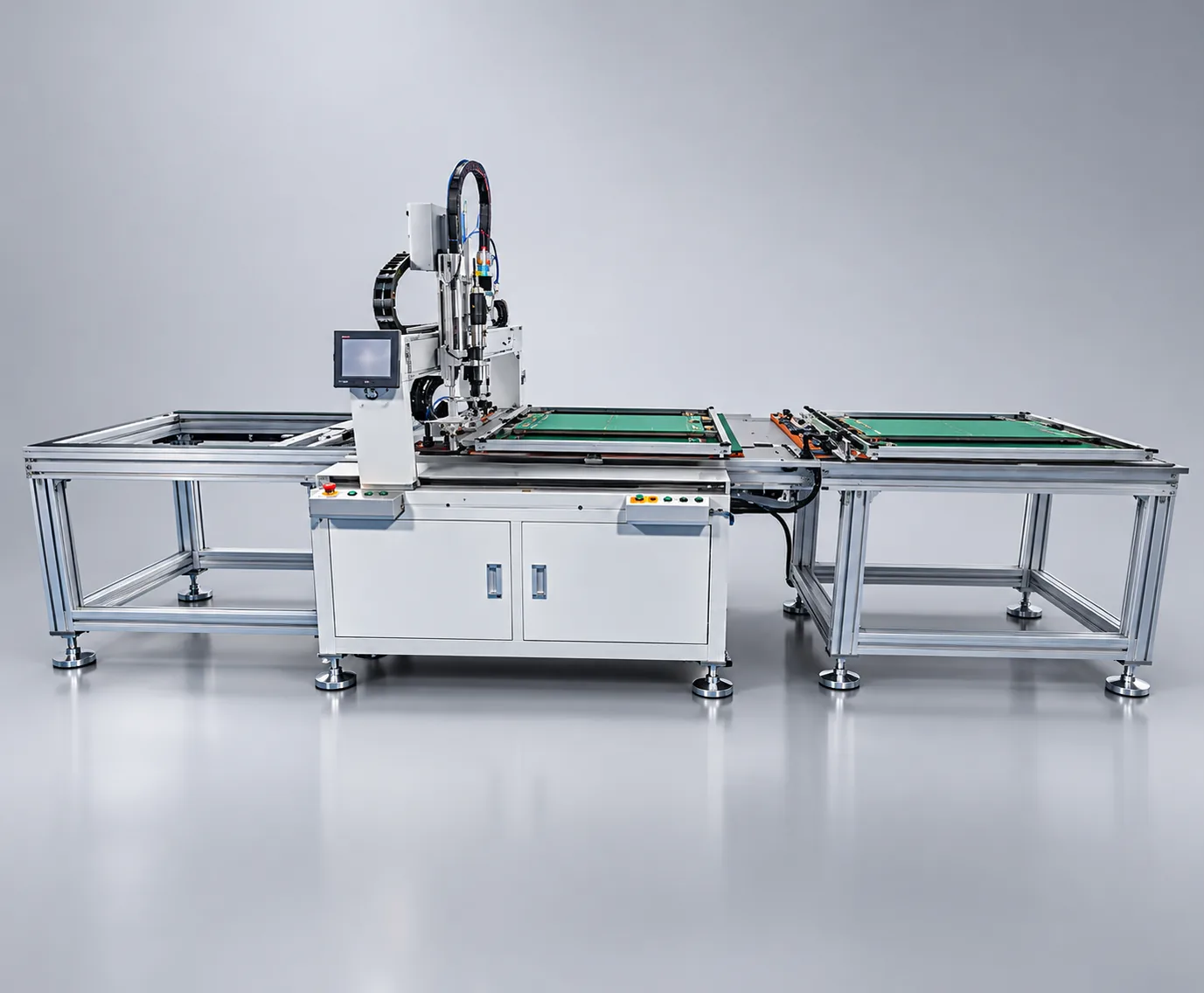
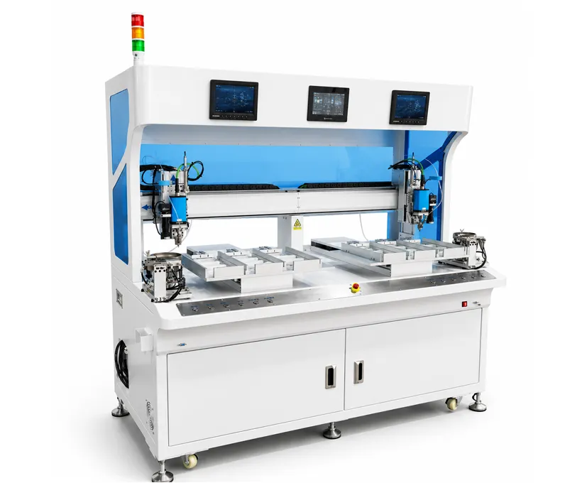
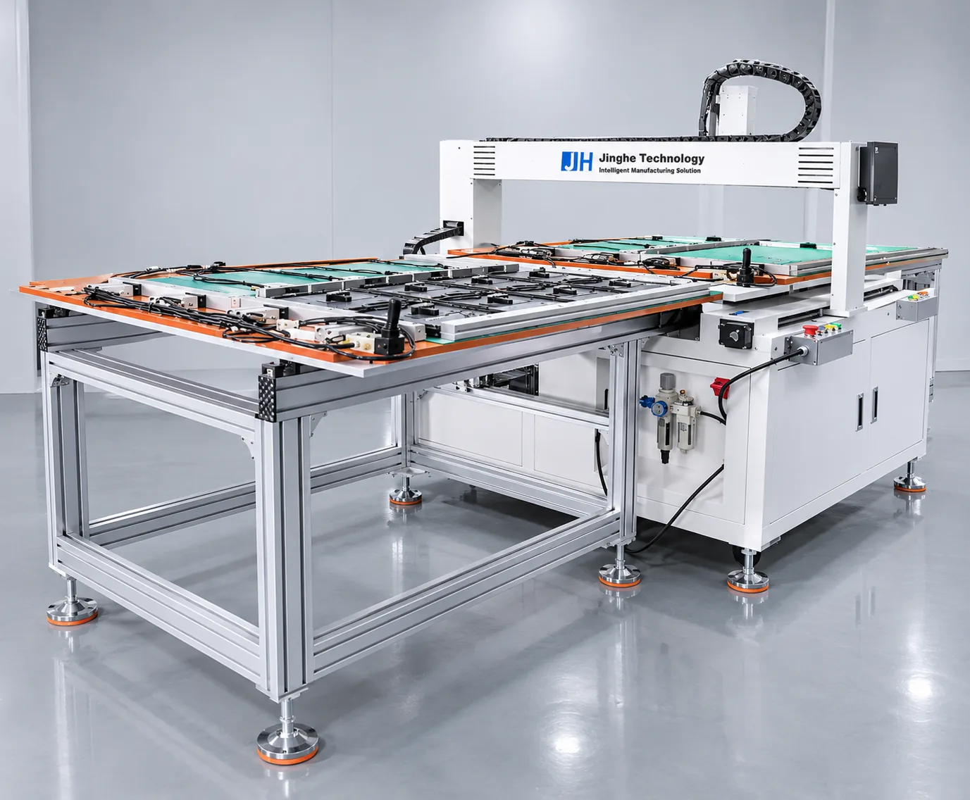
BL18 LED display cabinet screw fastening machine troubleshooting reference
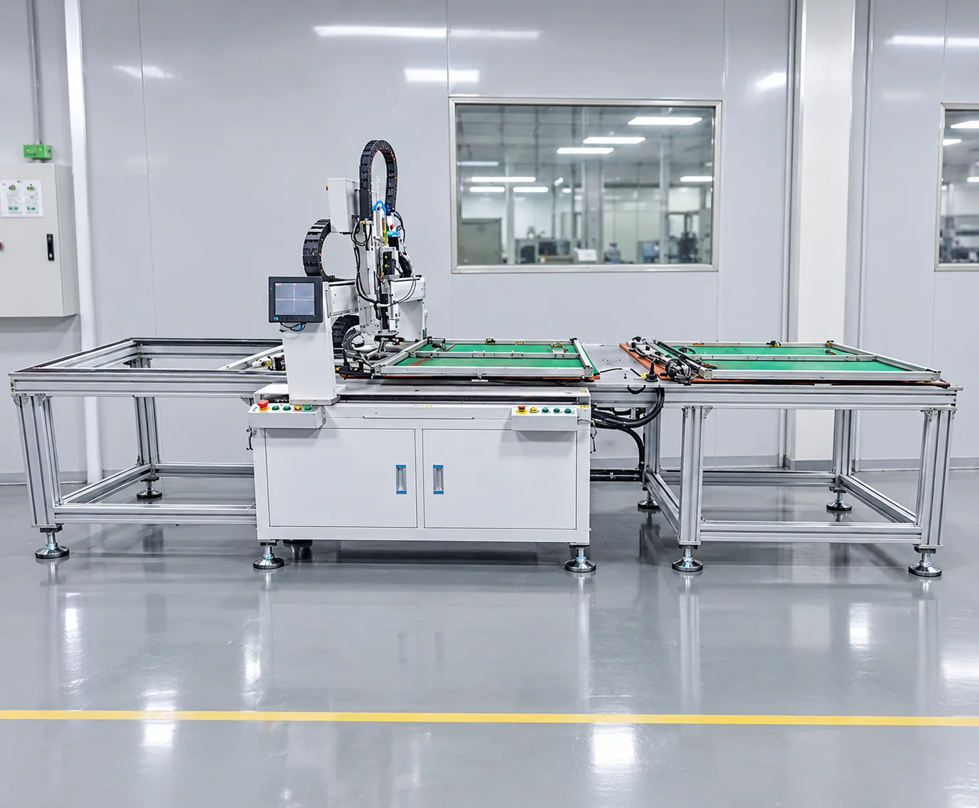
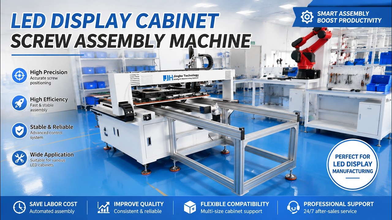
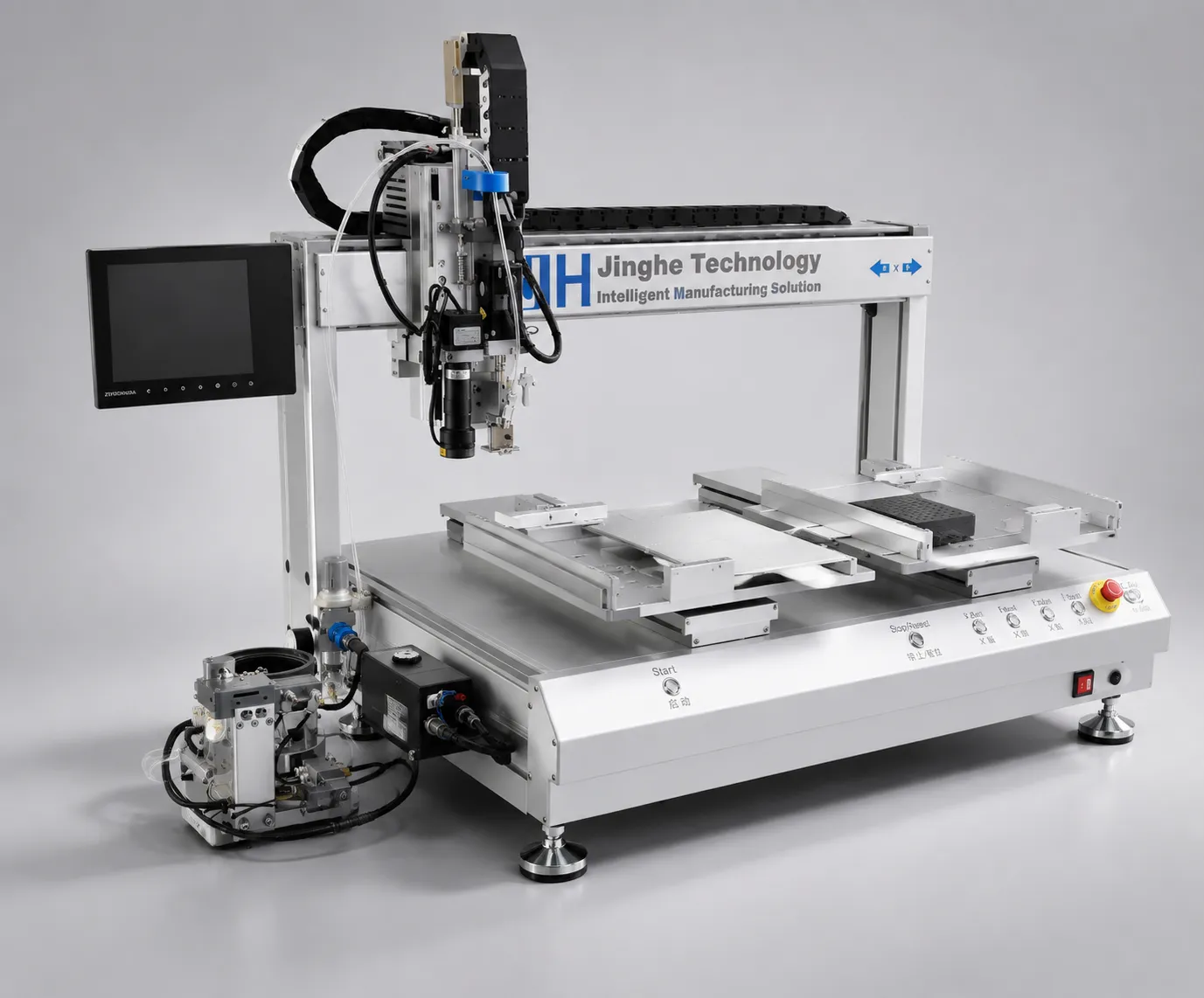
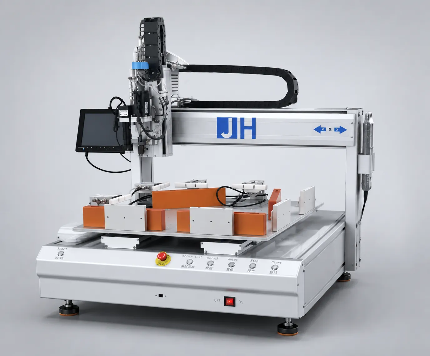
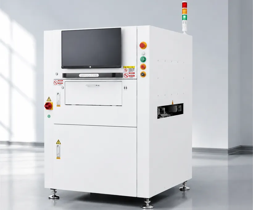
BL18 vertical four-axis LED display cabinet screw fastening machine.

60-Second Triage

Work through these three steps before changing a parameter. The goal is to identify the symptom, not to reset everything and lose the evidence.

  1. Confirm the alarm text. Read the exact message on the teach pendant or cabinet and note which fixture stopped.
  2. Find the matching symptom. Scan the categories below or the complete Symptom-to-Video table for the closest wording.
  3. Follow the video minute. Open the linked timestamp and repeat the demonstrated action on the BL18 before resuming production.

Start-up, Power & Display

The machine is on but nothing behaves as expected — language, alarms, reset, buttons, supply.

The teach pendant is in Chinese — how do I switch the BL18 to English?▼
Press More to open the main menu, go to the last page and open the Chinese-English version switch, then enter 2 for English and 1 for Chinese. Press the reset key afterwards to clear the alarm that the switch triggers. This is normal behaviour, not a fault, and the same menu path returns the machine to Chinese. ▶ Watch Part 0 at 00:12 — Watch at 00:12
An alarm appears the moment I change the interface language. Has something broken?▼
No. The language switch deliberately drops the machine out of its ready state, so the controller raises an alarm until you acknowledge it. Press the reset button on the pendant or the cabinet and the alarm clears immediately. Do not clear it by power-cycling the machine, and do not start a program before the alarm is gone. ▶ Watch Part 0 at 00:24 — Watch at 00:24
What is the difference between handle reset and machine reset?▼
Handle reset only returns the X, Y and Z axes of the working head. It does not move the conveyor or the fixtures. Machine reset, using the reset button on the cabinet, returns the three axes and the transport position, which is what you need before teaching a program. Use machine reset whenever the fixture must move back to a known station. ▶ Watch Part 2 at 00:52 — Watch at 00:52
I pressed reset but the axes still show values instead of zero. Why?▼
That means the reset did not complete. Check the pendant: X, Y and Z must all read 0 before you continue. If any axis still carries a value, the reset button was pressed too briefly or an axis is against a limit. Press machine reset again from the cabinet, not the handle, and confirm the zeros before teaching anything. ▶ Watch Part 2 at 01:18 — Watch at 01:18
What does each button on the cabinet do?▼
Left to right on the cabinet: start, start, reset, screw feeding, and drive the electric screwdriver. Identical buttons sit on the other side of the machine and mean exactly the same thing, so an operator can work from either side. A red emergency stop button is also fitted — pressing it halts every movement instantly, and the machine must be reset afterwards. ▶ Watch Part 2 at 01:28 — Watch at 01:28
What power and air supply does the BL18 need before first start-up?▼
Electrical supply is AC 220 V, 50 Hz through the supplied power cord. Compressed air connects at the blue quick coupling on the inlet; operating air pressure is 0.55-0.65 MPa. There is also a separate small gauge above the screw feeder. If either supply is outside its range the head will not pick screws reliably, so confirm both before blaming the program. ▶ Watch Part 2 at 00:27 — Watch at 00:27

Programs & Coordinates

Red parameters, servo configuration, teaching screw holes, Fixture 1 / Fixture 2 programs.

The parameter rows are shown in red and the servo configuration is missing. How do I restore them?▼
Delete the incomplete red rows, then press the key that restores all default parameters, and confirm with the More command key. The full default set, including the servo configuration that was missing, comes back and the text stops being red. Do not hand-type the values; restored defaults are the factory set and they match the machine’s mechanics. ▶ Watch Part 3 at 00:00 — Watch at 00:00
How do I create a new cabinet program?▼
Press Position 1 on the pendant and long-press until it flashes red so Fixture 1 moves to the fastening station. Press the switch button, open the folder, set the file number, confirm, then type the product name with the move-cursor key to change characters. The new program opens with default parameters and empty screw-hole coordinates ready to teach. ▶ Watch Part 2 at 03:44 — Watch at 03:44
How do I teach a screw-hole coordinate?▼
Move the working head over the hole with the X and Y jog keys, using the CCD camera view to centre it, then press the coordinate key marked 1 on the controller to record the point. Repeat for every hole. Move slowly near the product and always confirm the Z axis is raised, or the head will collide with the cabinet frame. ▶ Watch Part 3 at 02:22 — Watch at 02:22
Do I need two separate programs, one for Fixture 1 and one for Fixture 2?▼
Yes. The two fixtures are separate coordinate systems, so each fixture needs its own taught program. Build Fixture 1 first, then configure the I/O parameters and teach Fixture 2 the same way. Press Position 1 or Position 2 into position and select the matching program before you run, otherwise the head will fasten against an empty fixture. ▶ Watch Part 2 at 03:44 — Watch at 03:44
Which I/O values must be set for the second fixture?▼
Open More, go to page two, and choose the sixth option, Output Signal Programming. The output signal value must be set to 12 — 12 is the hardware interface number of that signal and it cannot be anything else. Set it once and the second fixture can be programmed and run. If this field is wrong, Fixture 2 will not fasten at all. ▶ Watch Part 4 at 00:30 — Watch at 00:30
How do I set the Z-axis fastening height?▼
Move the head over a screw hole, then press the Z-axis descend key. Slow the axis down as the head approaches the product and stop just above the surface, leaving a small gap rather than pressing the fixture. Press OK to store the height. Fast descent near the product is the most common cause of a crashed head and a damaged fixture. ▶ Watch Part 5 at 00:00 — Watch at 00:00
The cabinet has two different screw-hole depths. Can one program handle both?▼
Yes, but the Z-axis height for each depth must be set separately. Fasten one hole at the first depth, check the result, then set the second height and check again. Never copy one fixture’s Z height onto the other to save time — it will drive the head into the fixture and can damage the machine table. ▶ Watch Part 6 at 03:32 — Watch at 03:32
How many programs can the BL18 store?▼
Up to 1,000 program sets. Each program holds its own coordinates, Z heights and parameters, so you can keep a separate program per cabinet model and per fixture and simply call up the right number. Give each file a clear product name when you create it; that name is what you will search for months later. ▶ Watch Part 1 at 01:22 — Watch at 01:22
Where is the complete two-fixture program build shown end to end?▼
Part 16 is a thirty-minute walkthrough that builds a full dual-fixture program in one sitting: coordinates for both fixtures, the I/O entries, the Z heights, and the batch height edits. Use it after you have learned the individual steps in Parts 3 to 6, because it assumes you already recognise the menus. It ends with the program ready to run. ▶ Watch Part 16 at 00:00 — Watch at 00:00

Screw Feeding & Nozzle

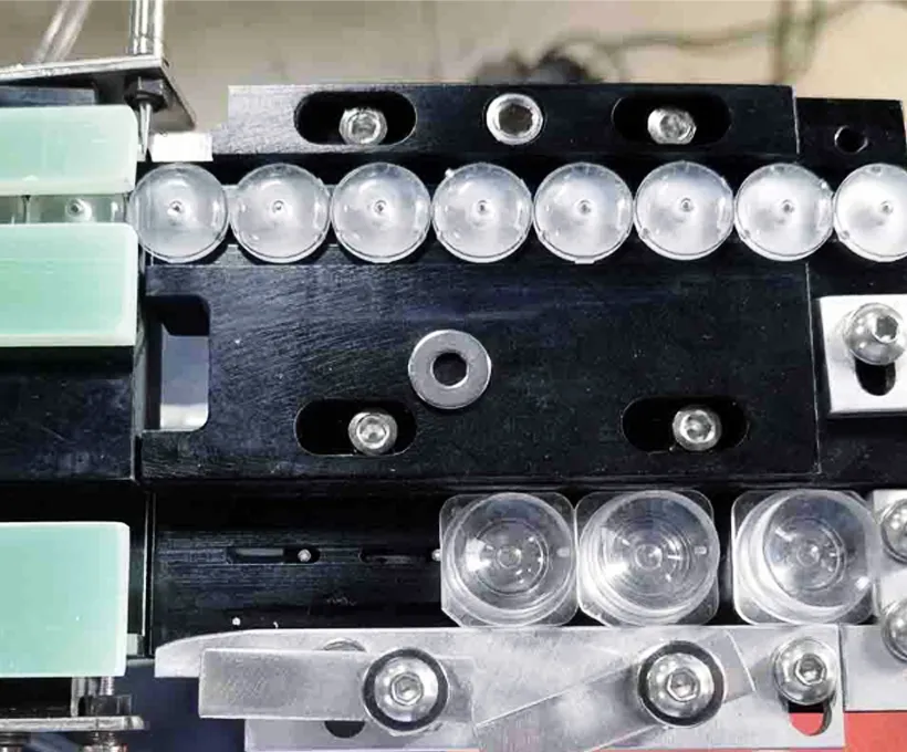
Jams, empty feeds, tilted screws, weak suction, worn nozzle, filter cotton.

A screw is jammed in the feeder and the machine has stopped. What is the fastest fix?▼
Stop the machine first. Open the feeder lid and look at the track where screws travel. Remove the stuck screw, check the upper gland height if screws keep clipping, then close up and use the screw-feed test switch. Clear any screw already sitting at the head before testing — two screws in that position will jam again immediately. ▶ Watch Part 10 at 00:01 — Watch at 00:01
How do I check that a screw will actually be blown out of the feeder?▼
Remove any screw already at the head, then press the screw-feed test switch and watch one screw arrive. Repeat two or three times. Good feeding means a screw appears every time. If it arrives irregularly the track or the gland height needs attention, not the program parameters, which are set at the factory. ▶ Watch Part 10 at 01:00 — Watch at 01:00
How many screws should I put in the feeder?▼
Add screws freely but never overfill. Too many screws stop the track from moving and cause repeated jams; the feeder then alarms continuously. Top up in smaller amounts and check the screw count each time. The feeder itself is set at the factory, so a jam is a loading or a track problem, not a parameter problem. ▶ Watch Part 9 at 01:35 — Watch at 01:35
The screw is blown down but lands tilted instead of standing in the hole. How do I fix it?▼
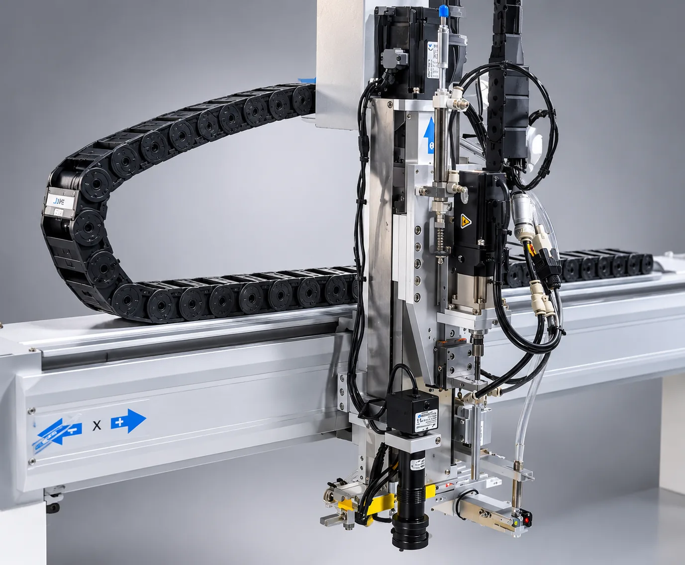
This is a nozzle position problem nine times out of ten. Press Preview Trajectory, switch to Output, move the cursor to 7 and press 1 to lower the nozzle, then check it sits directly over the hole. Loosen the nut to correct left-right offset, and the four lower screws to correct front-back offset, then tighten. ▶ Watch Part 11 at 00:00 — Watch at 00:00
The nozzle now sits too low and touches the frame or the sensor. How high should it be?▼
The nozzle must stop slightly higher than the cabinet cap so it can never collide, and slightly above the pick-up point so the screw still seats. Too low hits the sensor and alarms; too high and the screw will not feed into place. Adjust in small steps, blow a test screw each time, then fasten the adjusting screw so the position cannot drift. ▶ Watch Part 11 at 03:59 — Watch at 03:59
Suction has become weak and screws drop before reaching the hole. What should I check?▼
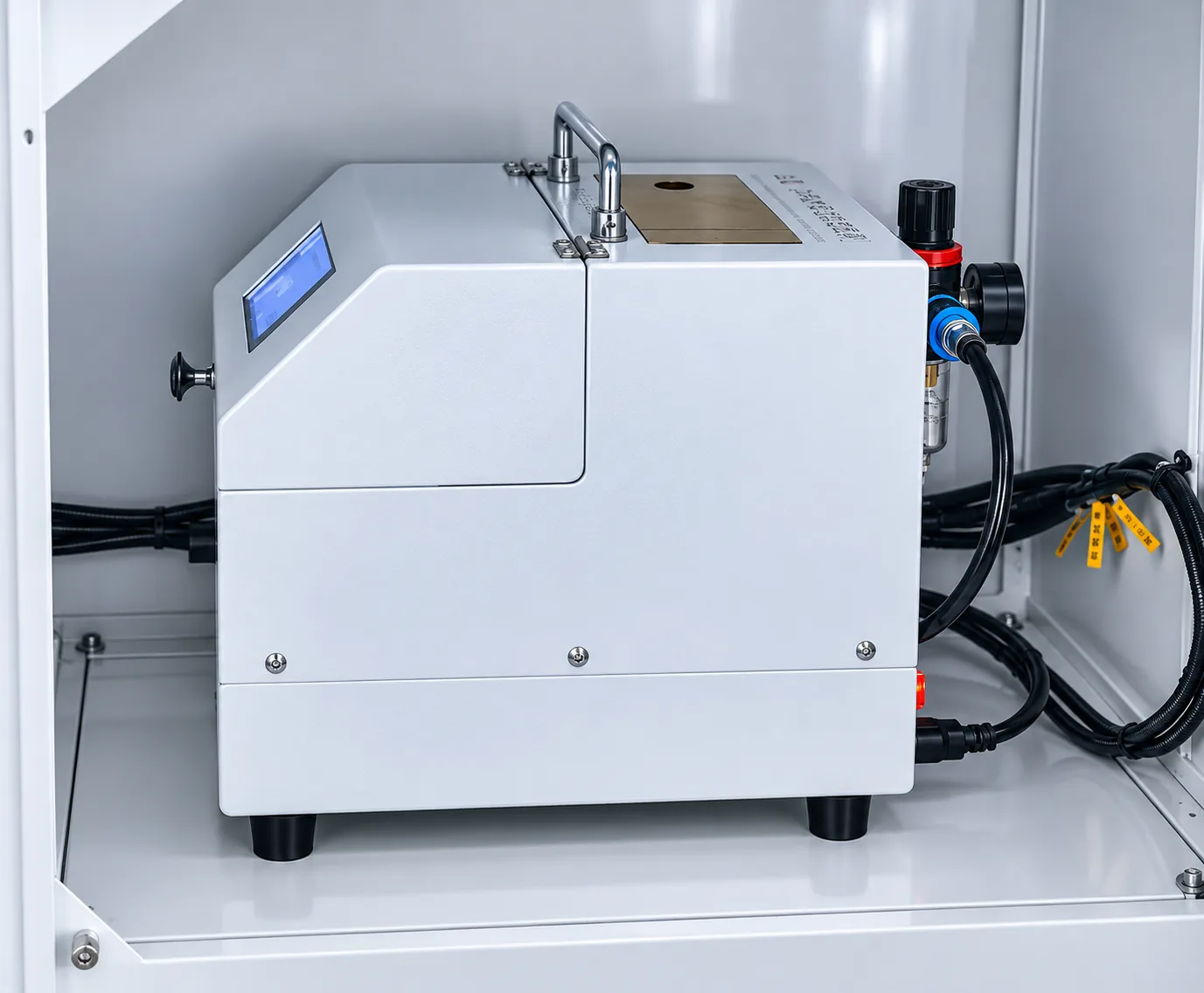
Check the filter cotton in the vacuum path first. If it is dirty the suction collapses. Unscrew the housing, pull the old cotton out and fit a new one with the arrow pointing upward — fitted upside down it will not draw at all — then push it fully home and close the clip. A loose or wrongly seated cotton also leaks air. ▶ Watch Part 12 at 02:55 — Watch at 02:55
How do I replace a worn suction nozzle?▼
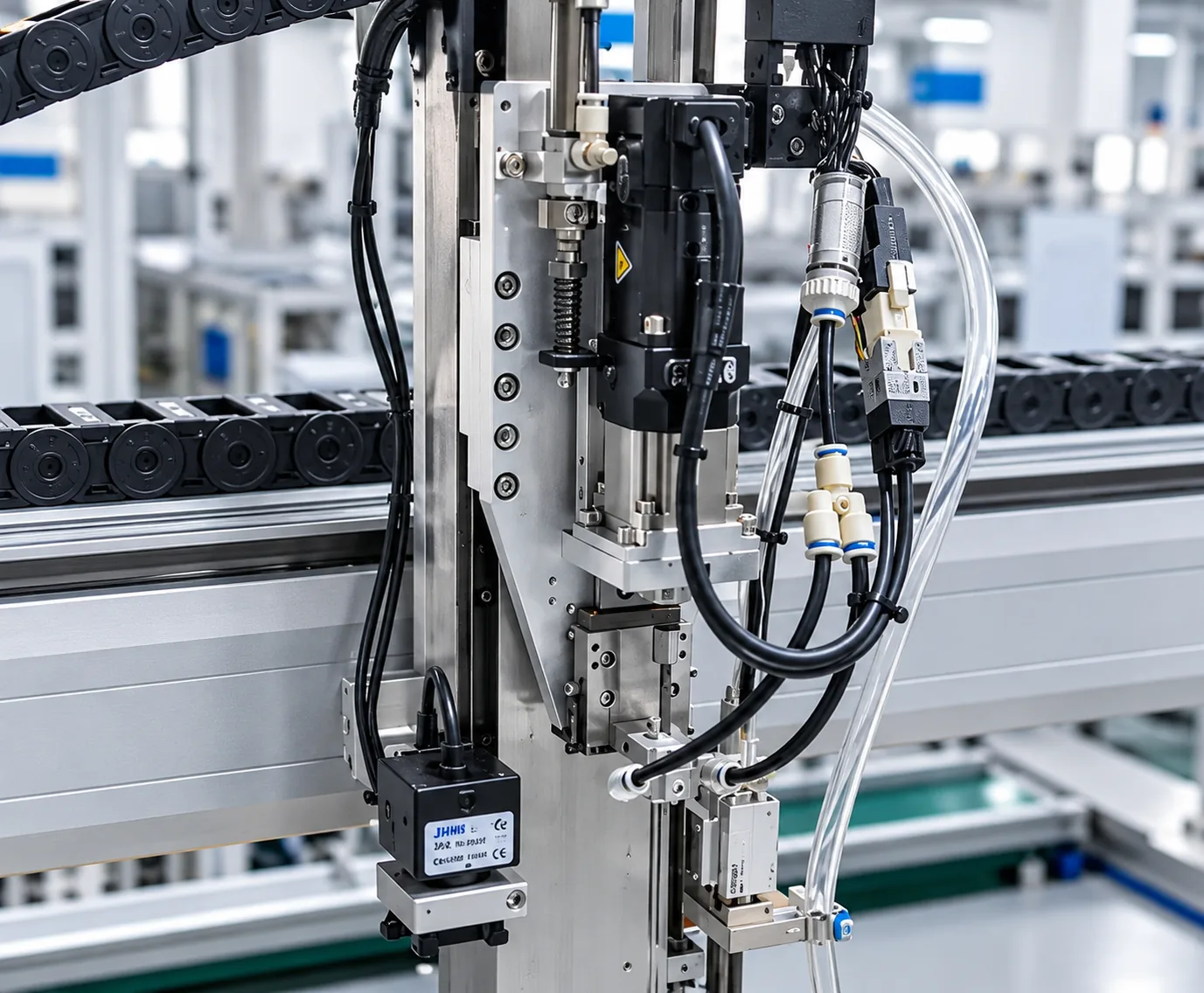
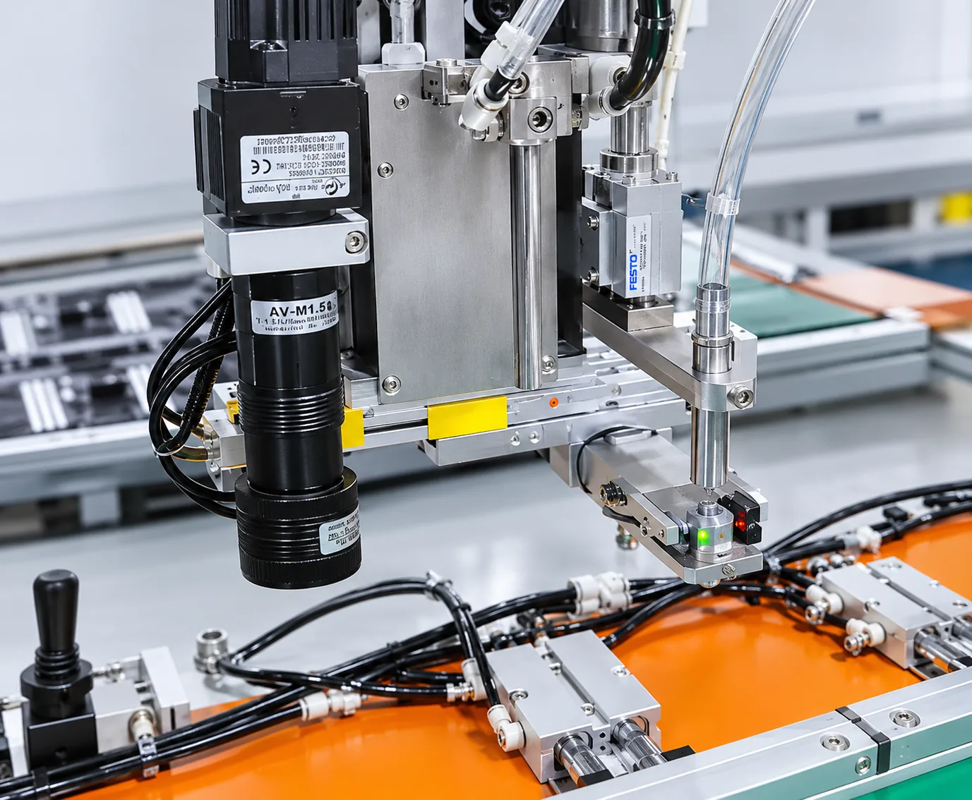
Loosen the M4 screw on the side of the holder and lift the clip to release the assembly. Disconnect the air tube by pressing the fitting in and pulling once — never pull it by force, the internal clip breaks. Fit the new nozzle, press it fully down until it seats, tighten firmly, then refit the clip with its tab aligned. ▶ Watch Part 12 at 00:00 — Watch at 00:00
What is the correct screw-pickup height, and how do I verify it?▼
Lower the nozzle slowly onto the pick-up point, leaving a small clearance rather than pressing the fixture, then press OK to store it. To verify, open the navigation screen, choose Machine Test and run item 6 to lift after picking, once with a screw and once without. A correctly centred screw in the nozzle means the height is right. ▶ Watch Part 17 at 00:35 — Watch at 00:35

Fastening Quality & Alarms

Loose screws, stripped threads, wrong torque, detection settings, speed and safety height.

Screws are coming out stripped. How do I stop it?▼
Turn on screwdriver completion detection and lower the tightening torque. Completion detection compares the torque actually reached against the target and stops the driver before a thread strips; torque set too high strips threads on soft cabinet material. Change only the tightening torque parameter, then run one test screw before resuming the whole program. ▶ Watch Part 15 at 01:50 — Watch at 01:50
Screws are not fully tightened and the cabinet still moves. What do I change?▼
Increase the tightening torque parameter, or check the floating-lock time, which should normally be 0.3 seconds. If the screw is not driven home the controller will alarm, and if floating-lock is too short the head releases before seating. Change one value at a time and confirm with a single test screw. ▶ Watch Part 15 at 01:05 — Watch at 01:05
Which detection options must be switched on?▼
Three: screwdriver completion detection set to 1, so torque must be reached; the alarm option set to 2, so a badly driven screw still alarms instead of the machine driving on; and screw-presence detection set to 2, without which the machine will drive with or without a screw in the nozzle. Use torque mode, not depth mode — this machine has no depth sensing. ▶ Watch Part 15 at 01:57 — Watch at 01:57
The machine keeps driving even though no screw is in the nozzle. Why?▼
Screw-presence detection is switched off. Set it to 2. Without it the controller cannot tell an empty nozzle from a loaded one, so it drives the head down onto the hole with nothing to fasten. That produces loose or missing screws and can mark the cabinet surface. Switch it on, then run one test screw. ▶ Watch Part 15 at 02:55 — Watch at 02:55
What axis speeds should I use, and can I make the machine faster?▼
Typical settings are X at 600, Y at 400 and Z at 400. The X axis maximum is 800. Raising the values does shorten cycle time, but speeds that are too high make the head arrive out of position and the screw land off-centre. If you change them, raise one axis at a time and re-check the first test screw. ▶ Watch Part 15 at 03:11 — Watch at 03:11
What is the safety height and why must it stay above the feeder?▼
Safety height is the Z height the head lifts to between screws, set to 155 on the BL18. It must clear the top of the feeder, because the feeder slides in underneath to deliver the next screw. If safety height is too low the head collides with the feeder, which is a hard mechanical stop and can bend the nozzle. ▶ Watch Part 15 at 03:51 — Watch at 03:51
What is floating-lock time for?▼
It holds the head against the cabinet briefly after the driver stops, letting the screw settle instead of springing back. The normal value is 0.3 seconds. It matters when screws are not driven down fully. It is not a fixed figure, so adjust it against your own cabinet material, but change only that one value at a time. ▶ Watch Part 15 at 01:04 — Watch at 01:04
How do I test one screw before running the whole cabinet?▼
Press Position 1, choose Single Step, select the first coordinate and press Single Step again. Watch the approach, check the screw sits flat and tight, then do the same for the second coordinate. Only after two good screws should you press Cursor Start to run the remaining holes automatically. If the head descends too fast, slow the cylinder. ▶ Watch Part 17 at 03:40 — Watch at 03:40
A stripped-thread alarm stopped the machine mid-cabinet. Can I skip just that hole?▼
Yes. Press Start and the machine skips that fastening point and continues with the rest, which is the correct response for a stripped thread or a hole that already contains a screw. Do not open the feeder to investigate — the feeder is fine. Skip the hole, finish the cabinet, and repair that single screw afterwards. ▶ Watch Part 10 at 02:35 — Watch at 02:35
Half the screws are already in. How do I continue from a later screw instead of starting over?▼
Press Position 1, find the next hole that still needs a screw, move the machine over it, then press Cursor Start followed by Start. The machine fastens from that point onwards and leaves the finished holes untouched. If no screw is waiting at the head, blow one into place first, then start from the cursor. ▶ Watch Part 18 at 00:00 — Watch at 00:00

Sensors & Machine Motion

No motion, magnetic switches, limit and position sensors, cylinder actions.

The machine will not move at all. Where do I look first?▼
Check the limit and position sensors. Each has an indicator light that must be on while the machine is running; if a light is off the controller refuses to move that axis. Loosen the sensor with a small wrench and slide it until the light comes on, then retighten. Also check the magnetic switches on the cylinders, which can work loose. ▶ Watch Part 11 at 12:41 — Watch at 12:41
The screen and pendant work but nothing responds to the start button.▼
Work through three things in order: confirm the machine is reset and all three axes read zero, confirm the emergency stop has not been pressed, and confirm the sensor lights for the axis you are trying to move. If a light is out, adjusting that sensor usually restores motion immediately. Note that the buttons on both sides of the machine are equivalent. ▶ Watch Part 11 at 12:28 — Watch at 12:28
How do I check the cylinder actions when something behaves inconsistently?▼
Watch the indicator lights on top of each cylinder while an operator cycles the machine in manual mode. A cylinder that should clamp but shows no light is not being commanded, which points to a magnetic switch out of position rather than a mechanical fault. Correcting the switch position is usually enough; the pneumatics themselves rarely fail. ▶ Watch Part 11 at 14:03 — Watch at 14:03

Cabinet Loading & Fixture

Clamping, module alignment, different cabinet sizes, one-cabinet testing, collision risks.

How do I load a cabinet so the screws land in the right place?▼
Place the LED module in the fixture with its edge against the fixed reference on the right, fit the die-cast aluminium frame over it, align module to frame, then flip the pneumatic clamping handle to clamp. Modules must sit close to the lower-right corner reference. Misaligned loading shows up as screws consistently offset in one direction. ▶ Watch Part 2 at 05:02 — Watch at 05:02
The cabinet moves or lifts while screws are being driven. What is wrong?▼
It is not clamped properly. Fastening requires a cabinet that cannot wobble at all, so check the clamping cylinder has actually closed and the clamping position suits this cabinet size. A module that is not clamped at the cylinder position is the classic cause of off-centre screws and of calibration that appears to drift afterwards. ▶ Watch Part 7 at 01:38 — Watch at 01:38
I need to run a different cabinet size. What must I adjust?▼
Move the clamping cylinder on the movable side to suit the new size, then fix it with its screws so it cannot slide. The BL18 handles cabinets up to the fixture limit and the two fixtures can carry different sizes — one larger cabinet on Fixture 1 and a smaller one on Fixture 2. Both screws in a cabinet must be identical. ▶ Watch Part 9 at 03:18 — Watch at 03:18
I only have one cabinet to test. Which fixture should I use?▼
Use Fixture 1 only. Set and test its program, and do not apply the same Z height to Fixture 2 while it is empty — with no cabinet present the head will travel to the fixture surface and damage the machine table. Run your single-cabinet tests on Fixture 1 until you have a second cabinet to load. ▶ Watch Part 6 at 07:04 — Watch at 07:04
How do I avoid crashing the head into the cabinet or the fixture?▼
Before running any program, walk every screw hole and remove anything that sits in the head’s path — module mounts, frame tabs, loose parts. Never move the X or Y axis while the Z axis is down. Reduce to slow speed as the head approaches the product, and treat the pre-run check as mandatory rather than optional. ▶ Watch Part 13 at 00:02 — Watch at 00:02
How does the dual-fixture cycle actually run?▼
While the right fixture is fastening at Station 2, you load the next cabinet on the left fixture at Station 1. When fastening finishes the fixture assembly shifts right, the finished cabinet arrives at Station 3 for unloading, and the newly loaded one moves into the fastening position. The machine therefore never waits for an operator to load, which is where the cycle-time gain comes from. ▶ Watch Part 8 at 00:00 — Watch at 00:00

Camera & Calibration

Dark camera view, knocked nozzle, bit-tip and camera calibration, screw sensor.

The camera view is too dark to see the screw holes. What do I adjust?▼
Rotate the CCD light-source brightness knob until the holes are clearly visible, then judge by what the pendant shows, not by the room. If the light does not come on at all, check the light’s power cords for a loose connector before assuming the lamp has failed. Brightness is an operator setting and needs no engineer visit. ▶ Watch Part 3 at 01:45 — Watch at 01:45
The nozzle was knocked and screws now miss the hole. What must be recalibrated?▼
Recalibrate the distance between the nozzle and the drill tip. Extend the drill head using Preview Trajectory then Output then item 6, lower it into a screw hole and centre it exactly, store the point, then bring the camera cursor to the same hole centre and confirm. The offset value then updates by itself and cannot be typed in manually. ▶ Watch Part 12 at 04:35 — Watch at 04:35
How does the vision camera get calibrated to the bit tip?▼
First clamp the cabinet, then align the extended bit head to the dead centre of a hole and confirm so the bit-tip coordinates are captured. The cursor then jumps to the camera item: raise Z to its highest position, move the camera over the same hole and align the red cursor to that centre. Confirm and the distance value updates automatically. ▶ Watch Part 14 at 00:04 — Watch at 00:04
The screw sensor no longer detects a screw in the nozzle.▼
Adjust the sensor rather than replacing it. With a screw present the red and green lights should be on together; with no screw only green. If it does not detect, loosen the mounting screw and slide the sensor slowly up or down until the yellow light comes on, then test again with a real screw. Never leave it adjusted so the light is off. ▶ Watch Part 11 at 07:17 — Watch at 07:17

Maintenance & Support

Lubrication, daily checks, consumable list, warranty, parts and who to contact.

Where and how often do I lubricate the BL18?▼
Clean the linear-guide sliders first, then oil the lead-screw sliders and run each block through its full travel so the oil distributes, and finally wipe away the used black residue. Lubrication applies to the guide sliders and lead-screw sliders on the axes. Doing it on a schedule is what keeps positioning at the rated accuracy. ▶ Watch Part 18 at 04:21 — Watch at 04:21
What consumables should I keep in stock?▼
Three: suction nozzles, filter cotton for the vacuum path, and the fastening screws themselves, M4×10 with flat and spring washers. Nozzles wear and get knocked, filter cotton clogs and quietly kills suction, and screws must be identical to each other. Changing either consumable requires rechecking nozzle position and, after a nozzle change, calibration. ▶ Watch Part 12 at 00:00 — Watch at 00:00
What should I check before every production run?▼
Four checks: the cabinet is clamped tight and cannot wobble, every screw hole is clear of obstacles in the head’s path, the feeder has screws and no jam, and the sensor lights are on. Part 13 states plainly that this check must be carried out before running a program. It takes under two minutes and prevents most crash damage. ▶ Watch Part 13 at 02:13 — Watch at 02:13
Why must both screws in a cabinet be identical?▼
Because the feeder, nozzle and torque are set for one screw specification. Mixed screws change the seating depth and the torque actually reached, so screws either strip or stay loose, and the detection options will alarm at random. The BL18 standard screw is M4×10 with flat and spring washers; if your product needs another specification, confirm it when ordering. ▶ Watch Part 13 at 01:18 — Watch at 01:18
What cabinet size and accuracy can the BL18 handle?▼
Maximum compatible fixture is 1024 x 1024 x 105 mm, and positioning accuracy is ±0.02mm, so cabinet modules of different thicknesses are all within reach thanks to the extended Z-axis stroke. The machine is 4700 x 1800 x 1500 mm and weighs about 550 kg. Confirm your own cabinet drawing against the fixture limit before ordering. ▶ Watch Part 1 at 00:15 — Watch at 00:15
What warranty and response time does JHIMS provide?▼
One year on the whole machine, with free after-sales repair or replacement for quality-related issues. Response is within 30 minutes; inside the Pearl River Delta a technician is dispatched within 24 hours, outside it within 48 hours depending on the situation. After-sales staff are on standby 24 hours a day, seven days a week, including public holidays. ▶ Watch Part 10 at 03:04 — Watch at 03:04
Who do I contact when the video and this page do not solve it?▼
Contact JHIMS engineering directly at [email protected] or on (86-755) 86700443, or through WhatsApp. Send the video part number you were following, the exact alarm text shown on the pendant, and which fixture the machine stopped on. The Part 10 video closes by asking customers to stop guessing and call rather than editing feeder parameters themselves. ▶ Watch Part 10 at 03:04 — Watch at 03:04

Symptom Finder — Screw Fastening Machine Troubleshooting

Every question appears once in this screw fastening machine troubleshooting table, ordered by its source category, with the exact video start time for the demonstrated repair.

Symptom Watch Which Video Start Minute Deep Link
The teach pendant is in Chinese — how do I switch the BL18 to English? Part 0 — BL18 training: Language, Alarm reset 00:12 Watch at 00:12
An alarm appears the moment I change the interface language. Has something broken? Part 0 — BL18 training: Language, Alarm reset 00:24 Watch at 00:24
What is the difference between handle reset and machine reset? Part 2 — BL18 training: Power on, Reset, Buttons, New program 00:52 Watch at 00:52
I pressed reset but the axes still show values instead of zero. Why? Part 2 — BL18 training: Power on, Reset, Buttons, New program 01:18 Watch at 01:18
What does each button on the cabinet do? Part 2 — BL18 training: Power on, Reset, Buttons, New program 01:28 Watch at 01:28
What power and air supply does the BL18 need before first start-up? Part 2 — BL18 training: Power on, Reset, Buttons, New program 00:27 Watch at 00:27
The parameter rows are shown in red and the servo configuration is missing. How do I restore them? Part 3 — BL18 training: Default parameters, Servo, Camera light, Teach coordinates 00:00 Watch at 00:00
How do I create a new cabinet program? Part 2 — BL18 training: Power on, Reset, Buttons, New program 03:44 Watch at 03:44
How do I teach a screw-hole coordinate? Part 3 — BL18 training: Default parameters, Servo, Camera light, Teach coordinates 02:22 Watch at 02:22
Do I need two separate programs, one for Fixture 1 and one for Fixture 2? Part 2 — BL18 training: Power on, Reset, Buttons, New program 03:44 Watch at 03:44
Which I/O values must be set for the second fixture? Part 4 — BL18 training: I/O, Output 12, Fixture 2, Z height 00:30 Watch at 00:30
How do I set the Z-axis fastening height? Part 5 — BL18 training: Z height, Drill head, Output 6 00:00 Watch at 00:00
The cabinet has two different screw-hole depths. Can one program handle both? Part 6 — BL18 training: Z height, Obstacles, Collision, Single step 03:32 Watch at 03:32
How many programs can the BL18 store? Part 1 — BL18 training: Overview, Capacity 01:22 Watch at 01:22
A screw is jammed in the feeder and the machine has stopped. What is the fastest fix? Part 10 — BL18 training: Jam, Slip alarm, Strip alarm, Resume 00:01 Watch at 00:01
How do I check that a screw will actually be blown out of the feeder? Part 10 — BL18 training: Jam, Slip alarm, Strip alarm, Resume 01:00 Watch at 01:00
How many screws should I put in the feeder? Part 9 — BL18 training: Feeder, Screws, Air, Fixture 01:35 Watch at 01:35
The screw is blown down but lands tilted instead of standing in the hole. How do I fix it? Part 11 — BL18 training: Tilted screw, Nozzle alignment, Sensor, Pickup height 00:00 Watch at 00:00
The nozzle now sits too low and touches the frame or the sensor. How high should it be? Part 11 — BL18 training: Tilted screw, Nozzle alignment, Sensor, Pickup height 03:59 Watch at 03:59
Suction has become weak and screws drop before reaching the hole. What should I check? Part 12 — BL18 training: Nozzle, Filter cotton, Calibration 02:55 Watch at 02:55
How do I replace a worn suction nozzle? Part 12 — BL18 training: Nozzle, Filter cotton, Calibration 00:00 Watch at 00:00
What is the correct screw-pickup height, and how do I verify it? Part 17 — BL18 training: Pickup height, Single step, Driving test 00:35 Watch at 00:35
Screws are coming out stripped. How do I stop it? Part 15 — BL18 training: Torque, Detection, Safety height, Speed 01:50 Watch at 01:50
Screws are not fully tightened and the cabinet still moves. What do I change? Part 15 — BL18 training: Torque, Detection, Safety height, Speed 01:05 Watch at 01:05
Which detection options must be switched on? Part 15 — BL18 training: Torque, Detection, Safety height, Speed 01:57 Watch at 01:57
The machine keeps driving even though no screw is in the nozzle. Why? Part 15 — BL18 training: Torque, Detection, Safety height, Speed 02:55 Watch at 02:55
What axis speeds should I use, and can I make the machine faster? Part 15 — BL18 training: Torque, Detection, Safety height, Speed 03:11 Watch at 03:11
What is the safety height and why must it stay above the feeder? Part 15 — BL18 training: Torque, Detection, Safety height, Speed 03:51 Watch at 03:51
What is floating-lock time for? Part 15 — BL18 training: Torque, Detection, Safety height, Speed 01:04 Watch at 01:04
How do I test one screw before running the whole cabinet? Part 17 — BL18 training: Pickup height, Single step, Driving test 03:40 Watch at 03:40
A stripped-thread alarm stopped the machine mid-cabinet. Can I skip just that hole? Part 10 — BL18 training: Jam, Slip alarm, Strip alarm, Resume 02:35 Watch at 02:35
Half the screws are already in. How do I continue from a later screw instead of starting over? Part 18 — BL18 training: Continue, Skip strip, Language, Lubrication 00:00 Watch at 00:00
The machine will not move at all. Where do I look first? Part 11 — BL18 training: Tilted screw, Nozzle alignment, Sensor, Pickup height 12:41 Watch at 12:41
The screen and pendant work but nothing responds to the start button. Part 11 — BL18 training: Tilted screw, Nozzle alignment, Sensor, Pickup height 12:28 Watch at 12:28
How do I check the cylinder actions when something behaves inconsistently? Part 11 — BL18 training: Tilted screw, Nozzle alignment, Sensor, Pickup height 14:03 Watch at 14:03
How do I load a cabinet so the screws land in the right place? Part 2 — BL18 training: Power on, Reset, Buttons, New program 05:02 Watch at 05:02
The cabinet moves or lifts while screws are being driven. What is wrong? Part 7 — BL18 training: Test screw, Clamping, Cursor start 01:38 Watch at 01:38
I need to run a different cabinet size. What must I adjust? Part 9 — BL18 training: Feeder, Screws, Air, Fixture 03:18 Watch at 03:18
I only have one cabinet to test. Which fixture should I use? Part 6 — BL18 training: Z height, Obstacles, Collision, Single step 07:04 Watch at 07:04
How do I avoid crashing the head into the cabinet or the fixture? Part 13 — BL18 training: Collision, Clamp, Cabinet size 00:02 Watch at 00:02
The camera view is too dark to see the screw holes. What do I adjust? Part 3 — BL18 training: Default parameters, Servo, Camera light, Teach coordinates 01:45 Watch at 01:45
The nozzle was knocked and screws now miss the hole. What must be recalibrated? Part 12 — BL18 training: Nozzle, Filter cotton, Calibration 04:35 Watch at 04:35
How does the vision camera get calibrated to the bit tip? Part 14 — BL18 training: Camera calibration 00:04 Watch at 00:04
The screw sensor no longer detects a screw in the nozzle. Part 11 — BL18 training: Tilted screw, Nozzle alignment, Sensor, Pickup height 07:17 Watch at 07:17
Where and how often do I lubricate the BL18? Part 18 — BL18 training: Continue, Skip strip, Language, Lubrication 04:21 Watch at 04:21
What consumables should I keep in stock? Part 12 — BL18 training: Nozzle, Filter cotton, Calibration 00:00 Watch at 00:00
What should I check before every production run? Part 13 — BL18 training: Collision, Clamp, Cabinet size 02:13 Watch at 02:13
Why must both screws in a cabinet be identical? Part 13 — BL18 training: Collision, Clamp, Cabinet size 01:18 Watch at 01:18
What cabinet size and accuracy can the BL18 handle? Part 1 — BL18 training: Overview, Capacity 00:15 Watch at 00:15
What warranty and response time does JHIMS provide? Part 10 — BL18 training: Jam, Slip alarm, Strip alarm, Resume 03:04 Watch at 03:04
Who do I contact when the video and this page do not solve it? Part 10 — BL18 training: Jam, Slip alarm, Strip alarm, Resume 03:04 Watch at 03:04
How does the dual-fixture cycle actually run? Part 8 — BL18 training: Workflow, Dual station 00:00 Watch at 00:00
Where is the complete two-fixture program build shown end to end? Part 16 — BL18 training: Programming, Dual Fixture 00:00 Watch at 00:00

19 Videos — Screw Fastening Machine Troubleshooting

JHIMS BL18 screw fastening machine training course — Part 0

Step Navigator

  1. Part 0 — Switch the teach pendant between Chinese and English; clear the alarm that appears after switching
  2. Part 1 — What the machine is, the dual-fixture three-station design, 1,000 x 1,000 mm capacity, 1,000 stored programs
  3. Part 2 — Power-on, 220V/50Hz supply, air inlet, handle reset vs machine reset, cabinet buttons, fixture Position 1/2, creating a new program
  4. Part 3 — Red/missing default parameters and servo configuration, CCD light brightness, teaching the first screw-hole coordinates, counter
  5. Part 4 — I/O Output Signal Programming (output fixed at 12), Fixture 2 screw-hole coordinates, start of Z-axis assembly height
  6. Part 5 — Set the Z-axis fastening height, slow-approach before contact, extend the drill head with Output 6
  7. Part 6 — Z height for two different hole depths, batch Z change, remove obstacles, never move X/Y with Z down, single-step test
  8. Part 7 — Drive test screws by hand and inspect them, what a not-clamped module looks like, start from the cursor
  9. Part 8 — The dual-fixture production cycle from load to unload
  10. Part 9 — Screw feeder location and power, how many screws to add, feeder barometer, adjust the fixture cylinder for 1000 x 500 and 1000 x 1000 cabinets
  11. Part 10 — Clear a feeder jam, use the feed-test switch, resume production after an exception, skip a stripped/slipped screw, why not to edit feeder parameters
  12. Part 11 — Fix a screw blown down tilted (nozzle left-right, front-back, height), screw-presence sensor, limit/position sensor, pickup height, machine test
  13. Part 12 — Replace the suction nozzle and the holder clip, replace the filter cotton, calibrate the nozzle-to-drill-tip distance
  14. Part 13 — Remove interfering parts before running, adjust the clamping position for 960 x 960 and 500 x 1000 cabinets, pre-run checklist
  15. Part 14 — Calibrate the distance between the vision camera and the bit tip
  16. Part 15 — Torque, screwdriver completion detection, screw-presence detection, floating-lock time, safety height, axis speeds
  17. Part 16 — Full dual-fixture program build end to end — coordinates, I/O, heights for both fixtures
  18. Part 17 — Verify the screw-pickup height, drive one screw with Single Step, then run the rest from the cursor
  19. Part 18 — Continue a half-finished cabinet from a later screw, skip a stripped hole, switch the interface language, lubricate the linear guides

This screw fastening machine troubleshooting index lists the complete official JHIMS video set in filming order. Click any part in the list to load it into the player above — no page reload, no jump to YouTube.

Contact Support

Tell us three things and we can answer without waiting for a site visit: the video number you were following, the exact alarm text on the pendant, and which fixture (1 or 2) the machine stopped on. Attach a photo of the pendant screen and a short clip of the fault — that is usually enough for our engineers to identify it in one reply.


After-sales · Engineering · Faults: [email protected]Phone: (86-755) 86700443WhatsApp: +86 189 7533 5491