Address
Building A1, Runteng Industrial Park, No. 4 Xishan Road, Longteng Community, Shiyan Subdistrict, Bao'an District, Shenzhen 518000, China
Work Hours
Monday to Friday: 7AM - 7PM
Weekend: 10AM - 5PM
Address
Building A1, Runteng Industrial Park, No. 4 Xishan Road, Longteng Community, Shiyan Subdistrict, Bao'an District, Shenzhen 518000, China
Work Hours
Monday to Friday: 7AM - 7PM
Weekend: 10AM - 5PM

Watch all 19 official JHIMS videos for the ZM500 screw tightening and removal machine, from first power-on to screw removal.
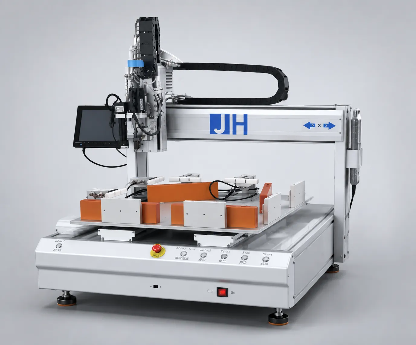
The complete operator course for the ZM500 three-axis screw tightening and removal machine – all 19 official JHIMS videos in the order they were filmed, from connecting power and air, clamping the first LED module and teaching screw coordinates, through camera calibration, depth and torque mode, to screw removal, re-locking and screw-size changeover.
Direct answer: The 19 videos below are the official JHIMS training series for the ZM500 screw tightening and removal machine, and every one of them plays inside this page. Video numbers on this page are the same as the YouTube Part numbers, so Part 7 is video 7. If the machine is new, watch videos 1 to 8 first – they cover hardware, the first program, coordinate teaching, calibration and depth mode. If you already run the machine, use the fault table further down to jump to the exact video and timestamp that fixes your problem.
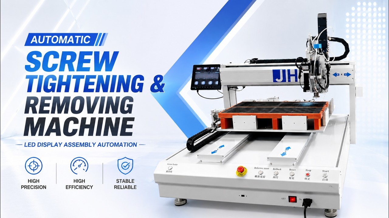
All 19 videos are the official JHIMS ZM500 series on our own YouTube channel – Parts 1 to 19, in filmed order, no third-party uploads.
Follow the five phases in order. Each video entry lists the procedure shown in that installment, followed by the notes stated in the source video.
Power, signal and air connections, the vibrating disk feeder, the pneumatic clamps, the CCD camera and the control panel.
Video 1 — Hardware tour: power, signal cables, air, feeder and control panel (9:40)
Key moments: 00:00 Power cord and signal cable connection · 00:19 Connect signal wires to screw feeder · 01:56 Air pressure input hose connection · 02:34 Screw feeder controller voltage and frequency · 04:16 Turn on machine main power
Note: The vibrating disk controller is set at the factory. Only the voltage (U) and frequency (F) may be adjusted – do not touch anything else on that controller (see video 9).
Note: Press Reset after power-on so the alarm clears and the head returns to origin, and press Reset again before switching the power off.
Video 9 — Hardware recap: feeder controller, clamps, camera and driver motor (8:12)
Key moments: 01:37 Change the display language · 02:09 Start wiring at the back panel · 02:22 Connect the main air inlet hose · 03:27 Adjust the vibrating disk controller (U/F) · 04:25 Clamp cylinder on LED module
Note: The air tube must pass through the sensor before it reaches the head – if it is routed outside the sensor, the machine cannot see the screw arriving.
Note: Voltage and frequency on the feeder controller were set before shipment; changing them is the most common cause of screws no longer feeding evenly.
Switch the controller to English, set the default parameters, adapt the fixture to the module size and create a named program.
Video 2 — Switch the controller to English and set the first program parameters (9:25)
Key moments: 00:06 Open Menu 4 for language setup · 00:29 Switch controller to English language · 04:37 Enter 1 to clamp the product · 05:14 Align red cursor to screw hole center · 05:49 Record first coordinate with Location key
Note: Entering the language menu is the same key combination on every ZM500: Stop + Menu 1, then Menu 4.
Note: The product must be clamped before you teach any coordinate, otherwise every position you record is wrong.
Video 3 — Adapt the fixture to the LED module size and create a named program (12:13)
Key moments: 00:06 Loosen screws to move cylinder fixture · 02:18 Open Menu 3 to clamp module · 03:41 Start creating a new program · 05:22 Switch input method for program name · 07:57 Set follow-up length to zero
Note: The maximum product size for the ZM500 is L500 × W500 mm; the cylinder fixture can be moved anywhere inside that envelope.
Note: If the module is not flat before clamping, coordinates taken afterwards will be off by the amount the module is tilted.
Video 10 — Prepare screw removal: clamp, change the nozzle and start a program (8:20)
Key moments: 00:06 Start removing screws from plate · 00:53 Adjust fixture with cylinder clamped · 03:59 Begin nozzle change for screw removal · 06:06 Install air tube before removing screws · 07:24 Switch input method to type product name
Note: If the removal part does not seat, loosen the small screw on the holder rather than forcing the part – forcing it deforms the bit.
Note: Adjusting the cylinder after clamping is what keeps the product from moving while the screws are backed out.
Find each screw hole through the CCD camera, record it with the handle, copy identical hole patterns in bulk, then calibrate the camera against the head.
Video 4 — Programming part 1: clamp the module and teach each screw hole with the CCD camera (17:07)
Key moments: 00:32 Release cylinder clamp with reset · 01:55 Change option 5 value to clamp · 02:53 Insert screw removal command · 09:07 Center cursor on first screw hole · 14:00 Recheck and correct stored coordinates
Note: If the coordinates of a hole are offset, the screw cannot be assembled or removed properly – the crosshair must be in the centre of the hole, not at its edge.
Note: For LED modules, remove or lift the mask when it hides the holes; video 5 shows the shortcut of teaching from a module that already has screws in it.
Video 5 — Fast programming: copy one screw pattern onto the identical section (8:02)
Key moments: 00:43 Introduce the copy coordinate method · 02:14 Move CCD to first lower screw hole · 04:00 Press 1 to select copy option · 05:59 Copy upper coordinates below line 39 · 07:09 Recenter each copied screw coordinate
Note: Bulk copy only works when the second area has the same hole spacing as the first – irregular patterns must be taught hole by hole (video 13).
Note: Even a correct copy needs a visual check: one offset hole is one screw that will not go in.
Video 6 — Calibrate the CCD camera against the head (7:42)
Key moments: 01:00 Open Menu 4 for calibration · 01:45 Calibrate camera to head distance · 04:39 Drill marker with both buttons · 05:58 Locate drilled marker with CCD · 07:15 Press Enter to confirm calibration
Note: Re-calibrate whenever the camera has been removed or knocked, when the nozzle has been changed, or when the assembly position looks inaccurate – the whole purpose of the calibration is to re-establish the camera-to-head distance.
Note: A bent or deformed nozzle bit also needs calibration after replacement.
Video 11 — Teach coordinates with the handle: speeds, crosshair and the record key (15:16)
Key moments: 00:01 Begin teaching screw coordinates · 00:38 Adjust camera focus for clear view · 01:11 Switch slow speed near screw hole · 01:52 Record first coordinate with key 1 · 13:01 Insert screw removal instruction
Note: Pressing 1 multiple times in a row records duplicate coordinates – one press, one hole.
Note: The same coordinate procedure is used for assembly and for removal; the mode is set later in the parameters, not while teaching.
Video 13 — Record all hole coordinates and bulk-copy a block to the next section (11:09)
Key moments: 01:03 Press 1 to record coordinate · 02:54 Demonstrate batch copying screw coordinates · 03:50 Choose copy option in menu 1 · 05:48 Realign copied coordinates to screw centers · 07:59 Demonstrate wrong operation duplicating coordinates
Note: Bulk copy is invalid for irregular hole patterns – if the spacing differs, teach the holes individually.
Note: When you copy, verify that the destination spacing matches the source spacing before you accept it.
Set the Z-axis height, choose depth mode or torque mode, set the drill-bit service-life limit, check the default parameters and run the program – including how to skip a screw after an alarm.
Video 7 — Set the Z-axis assembly height and choose depth mode or torque mode (10:49)
Key moments: 00:22 Slowly lower Z axis to surface · 02:27 Bulk edit all Z axis heights · 04:02 Select depth mode in Menu 4 · 06:00 Restart machine to apply mode · 07:45 Start torque value at 0.03
Note: Depth mode stops the driver when the sensor detects the telescopic column; torque mode stops it when the set torque is reached. Never mix the two settings within one program.
Note: The white press must only touch the LED surface – pressing it down changes the height you just recorded.
Video 8 — Run the program, and skip a screw after a depth alarm (13:33)
Key moments: 01:18 Open page 2 option 7 in menu 3 · 01:37 Set option five to 1 for cylinder clamp · 02:20 Switch camera motion to drill motion · 04:37 Read sensor light to find drill stop · 07:32 Rotate telescopic ruler to set tightening depth
Note: A depth abnormality means the screw was not tightened to the set depth – the machine stops rather than driving it further. Skipping is safe for that one screw, but mark it for re-check.
Note: Do not leave a skipped screw unrecorded: the customer-facing board must not ship with a loose screw.
Video 12 — Drill-bit service-life limit, motor test and CCD reference point (13:23)
Key moments: 00:00 Set drill bit service life limit · 05:27 Open menu 4 with stop plus menu 1 · 06:25 Select depth mode by entering 1 · 08:36 Adjust torque value in option four · 09:52 Power off after torque parameter setting
Note: The bit-life counter is a reminder, not a measurement: the machine cannot see wear. Inspect the bit when it alarms.
Note: Choosing the wrong reference (camera versus nozzle) is a common reason taught coordinates suddenly land off-centre.
Video 17 — Default parameter reference: assembly versus removal (3:01)
Key moments: 00:08 Set follow-up speed parameter · 00:51 Turn on screw detection setting · 01:22 Close locks screws, open removes · 02:32 Raise removal height to 15 or 20 · 02:49 Enable screw removal switch
Note: The removal switch must be entered as 1 to remove screws and 0 to drive them – a wrong value is the usual reason a removal run does nothing.
Note: Check the removal height against the product before every removal run: too low and the head hits the module.
Video 18 — Torque-mode assembly: telescopic column and torque value (4:40)
Key moments: 00:00 Screw telescopic column out of sensor · 00:53 Select 0 for torque mode · 01:15 Open intelligent batch settings option 7 · 02:32 Lower torque parameter to 0.04 · 03:33 Press OK to save parameters
Note: 0.15 N·m is already a high value for these screws; work up from a low torque instead of starting high.
Note: In torque mode the depth sensor must stay untriggered, otherwise the machine stops before the torque is reached.
Change the head for removal, run removal from the cursor, re-lock the screws afterwards, switch a removal program back to assembly and rebuild coordinates after a fixture change.
Video 14 — Set the Z-axis height, then run screw removal from the cursor (6:09)
Key moments: 00:09 Set Z-axis coordinates for assembly · 02:27 Enter Z-axis height value 68.6 mm · 03:11 Test one screw in single-step mode · 04:32 Set max lock time to 0.5 for removal · 05:30 Run from cursor to remove remaining screws
Note: The nozzle should hang slightly above the LED surface, not press on it – the driver still has travel when it comes down.
Note: Run from cursor continues from the current coordinate, so a wrong cursor position means the machine starts at the wrong screw.
Video 15 — Re-lock after removal, and change feeder parts for a different screw size (9:00)
Key moments: 00:09 Swap the nozzle · 00:42 Lift fixture and insert the drill · 01:42 Replace the screw conveyor air tube · 05:34 Replace feeder parts for new screw size · 07:30 Install M1.0 screw track
Note: An air tube that is not pushed to the bottom is a classic cause of screws failing to reach the head.
Note: Changing the screw size means changing feeder parts and bit together – a mismatched bit damages both the screw head and the bit.
Video 16 — Convert a removal program back to assembly (15:49)
Key moments: 00:07 Change locking time to 1.5 seconds · 01:15 Turn off screw-removal mode · 03:56 Copy the program to the controller · 07:33 Enter Z-axis height 60.8 · 14:46 Run from cursor for remaining screws
Note: Assembly and removal share the coordinate list but not the timing: the removal time and the locking time are set separately.
Note: Do not move the clamp cylinder up and down too fast – it shifts the product and the taught coordinates no longer fit.
Video 19 — Rebuild coordinates after a fixture change and continue the run (13:22)
Key moments: 00:15 Disable screw-removal mode · 00:48 Coordinates shifted after fixture added · 02:18 Select option 9 to teach offset · 09:12 Increase torque from 0.04 to 0.045 · 12:45 Run from cursor to finish assembly
Note: Adding or moving the fixture changes the product position, so previously taught coordinates are no longer valid – re-teach rather than adjust one hole.
Note: A single-step test at the first screw confirms the rebuilt program before the automatic run.
Everything below comes from the product specification and from the training videos. Check it before the first screw and after any change of product, screw size or fixture.
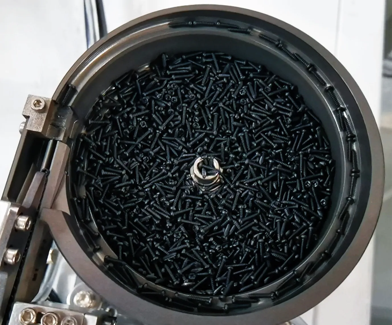
Note: The ZM500 stores up to 1,000 programs, so keeping one program per product is the fastest way to change over: recall, clamp, run.
Video numbers are identical to the YouTube Part numbers. Use this table to decide which video you need before you start watching.
| Video | Phase | Topic | You can do this afterwards |
|---|---|---|---|
| Video 1 | Phase 1 | Hardware tour: power, signal cables, air, feeder and control panel | Identify every component of the ZM500 and make the electrical, signal and pneumatic connections correctly. |
| Video 2 | Phase 2 | Switch the controller to English and set the first program parameters | Open the parameter menus, change the interface language and enter the default values the ZM500 needs before teaching a program. |
| Video 3 | Phase 2 | Adapt the fixture to the LED module size and create a named program | Move the pneumatic clamps and support blocks to suit the module, then save the job under its own program name. |
| Video 4 | Phase 3 | Programming part 1: clamp the module and teach each screw hole with the CCD camera | Record the screw-hole coordinates one by one, using the camera crosshair and the handle keys. |
| Video 5 | Phase 3 | Fast programming: copy one screw pattern onto the identical section | Cut programming time by copying an already-taught block of coordinates onto a second, identical area of the same product. |
| Video 6 | Phase 3 | Calibrate the CCD camera against the head | Teach the machine where the camera is relative to the nozzle, so every taught coordinate really lands on the screw hole. |
| Video 7 | Phase 4 | Set the Z-axis assembly height and choose depth mode or torque mode | Set the height at which the screw is driven, and understand the difference between depth mode and torque mode. |
| Video 8 | Phase 4 | Run the program, and skip a screw after a depth alarm | Finish the parameter set, run the program and recover from the alarms ZM500 raises while running. |
| Video 9 | Phase 1 | Hardware recap: feeder controller, clamps, camera and driver motor | A second, closer walkthrough of the components – useful when you are checking a connection you are not sure about. |
| Video 10 | Phase 2 | Prepare screw removal: clamp, change the nozzle and start a program | Turn the machine from driving screws to removing them, and confirm the product sits flat before you record anything. |
| Video 11 | Phase 3 | Teach coordinates with the handle: speeds, crosshair and the record key | Use the handle correctly – speed switching, X/Y jog keys and the single-press rule for recording a hole. |
| Video 12 | Phase 4 | Drill-bit service-life limit, motor test and CCD reference point | Set the bit-life counter and know which recovery key to use for each alarm. |
| Video 13 | Phase 3 | Record all hole coordinates and bulk-copy a block to the next section | Complete a full coordinate set and copy a range of coordinates onto the following serial numbers. |
| Video 14 | Phase 5 | Set the Z-axis height, then run screw removal from the cursor | Set the height reference for assembly and start an automatic removal run from the current position. |
| Video 15 | Phase 5 | Re-lock after removal, and change feeder parts for a different screw size | Put the screws back in after a removal run, and convert the feeder and head to a different screw size. |
| Video 16 | Phase 5 | Convert a removal program back to assembly | Reuse a program you built for screw removal, so it drives screws instead of backing them out. |
| Video 17 | Phase 4 | Default parameter reference: assembly versus removal | Read the default parameter screen and know which values belong to driving screws and which to removing them. |
| Video 18 | Phase 4 | Torque-mode assembly: telescopic column and torque value | Run the machine in torque mode – sensor not triggered, torque raised gradually until the screw is tight. |
| Video 19 | Phase 5 | Rebuild coordinates after a fixture change and continue the run | Recover a program whose coordinates no longer match the product after the fixture was changed. |
Symptoms in the order operators report them, with the video and the timestamp that addresses each one. Give the video number and the timestamp when you contact our engineers – it saves a round of questions.
| Symptom or alarm | Most likely cause | What to do | Video |
|---|---|---|---|
| Screws stopped feeding, no screw at the head | Screw jammed in the delivery tube, or the tube is not pushed to the bottom of its fitting | Press the white buckle and push the air tube fully into the bottom of the fitting, check the feeder track, then resume | 15 |
| Feeder vibrates but no screws come out | Vibrating disk voltage or frequency was changed | Restore U and F to the factory values – only U and F are adjustable on that controller | 9 |
| Machine alarms after a set number of screws | Drill-bit service-life counter reached its limit | Inspect the bit; if it is still good, raise the limit in the bit-life setting | 12 |
| Slipping / sliding-tooth screw alarm | Screw not seated, bit worn, or the drive was interrupted | Clear the screw at the head; if the screw is already driven press Start, if not use the motor test switch | 12 |
| Depth abnormality alarm mid-run | Screw did not reach the set depth | Press Start once to skip that screw and continue; mark the skipped screw for re-check | 8 |
| Tightened screws still loose in torque mode | Torque too low, or the telescopic column is being sensed | Screw the column down so the sensor is not triggered, then raise the torque step by step and test | 18 |
| Screws land off-centre | Coordinate not centred, or the camera/nozzle reference point is wrong | Re-centre the crosshair and press Location; check the CCD point setting | 4 / 12 |
| All coordinates wrong after a fixture change | Product position moved with the fixture | Rebuild the coordinate list for the new position, then run from the cursor | 19 |
| Removal run does nothing | Screw-removal mode not switched on | Set the screw-removal mode to 1 (0 drives screws, 1 removes them) | 17 |
| Removal head hits the product | Removal height set too low | Raise the removal height – 15 or 20 is used in the video when the head touches | 17 |
| Head collides or drops onto the product | Power switched off without homing | Press Reset before switching the power off, every time | 1 / 2 |
| Machine will not move after power-on | Alarm raised at start-up | Press the reset button – the head returns to origin and the alarm clears | 2 |
The parts you will replace during normal operation, and where each change is demonstrated. Screw-size changes move three feeder parts and the bit together.
| Part | When to replace or check | Demonstrated in |
|---|---|---|
| Driver bit | At the service-life limit set in the controller, or as soon as screw heads start to cam out | 12 |
| Nozzle (assembly) | When the nozzle is knocked, deformed or does not hold the screw square | 1, 10 |
| Screw-removal part | Fitted for removal jobs, removed again for assembly | 10, 15 |
| Feeder parts for the screw size | Whenever the screw size changes – M0.8, M1.0 and M1.7 need their own parts | 15 |
| Air delivery tube | When a screw no longer reaches the head; reseat to the bottom of the fitting | 15 |
| Support blocks and clamp position | Every product changeover | 3, 10 |
| Camera-to-head calibration | After removing or knocking the camera, or after any nozzle change | 6 |
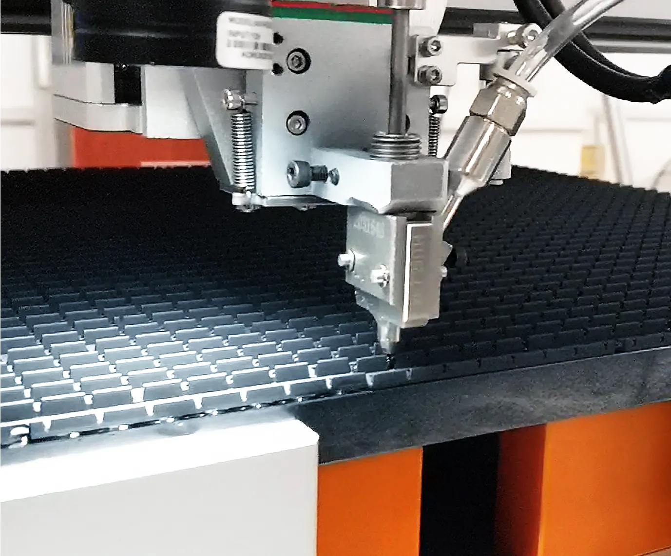
The ZM500 uses the same coordinates and the same gantry for assembly and for removal. Four things change, and all four are shown in videos 10 to 19.
Note: After a removal run, re-lock the screws with the assembly nozzle (video 15), and always check the bit before driving a full pattern again.
Values as published on the ZM500 product page – use these, not the values you may remember from an older machine.
| Item | Specification | Item | Specification |
|---|---|---|---|
| Model | ZM500 | Screw specification | M0.8–M1.7 |
| Number of axes | 3+1 axes (Y-axis auxiliary) | Positioning accuracy | ±0.025 mm |
| Repeatability | ±0.025 mm | Compatible product size | L500 × W500 mm |
| Locking efficiency | 0.9–1.2 s per screw | Simultaneous drivers | 1 (servo electric driver) |
| Effective travel (X/Y/Z) | 520 × 520 × 100 mm | Overall dimensions | 960 × 900 × 750 mm |
| Machine weight | Approx. 110 kg | Control method | Control card + handle |
| Power supply | AC 220V, 50 Hz | Working air pressure | 0.55–0.65 MPa |
| Feeding method | Blow-type (pneumatic) | Feeder type | Precision vibrating disk |
| Program storage | 1,000 programs | Display | Touch screen |
| Alignment method | Camera-assisted | Fixture mode | One-to-one |
| Alarm functions | Slippage, feeding abnormality | Depth detection | Built-in sensor module |
These answers use the same video numbers and timestamps as the 19-part ZM500 series above.
This machineJHIMS ZM500 Screw Tightening & Removal MachineThree-axis machine for driving and removing M0.8–M1.7 screws on LED modules up to 500 × 500 mm.Open →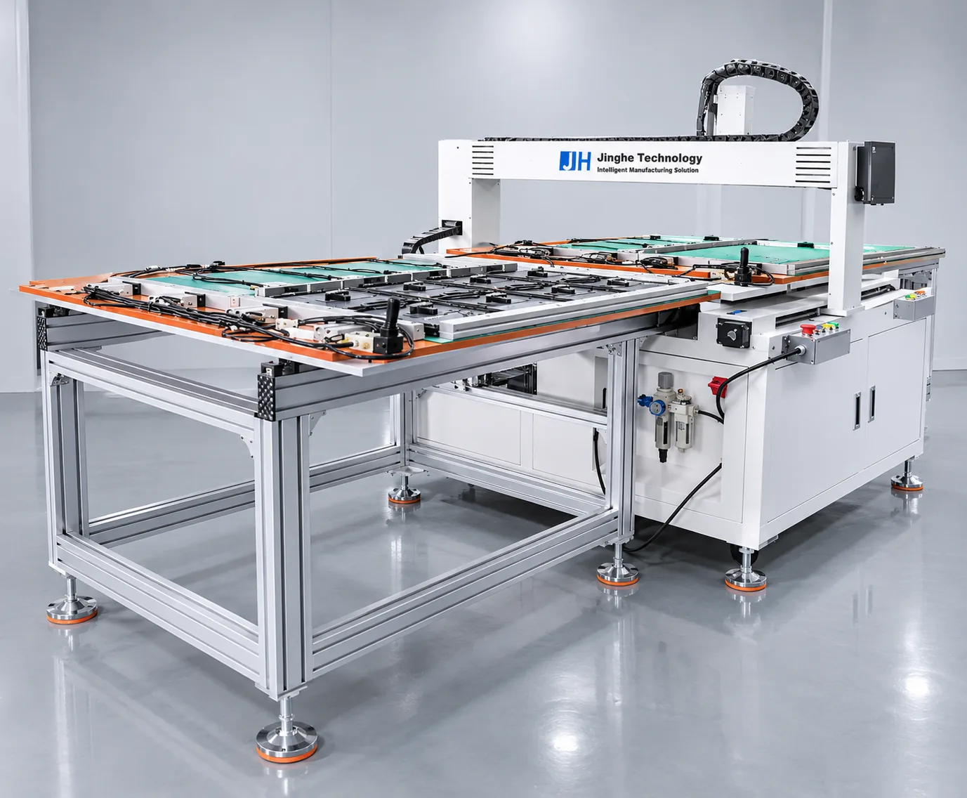 Screw fasteningJHIMS BL18 Vertical 4-Axis LED Display Cabinet Screw Fastening MachineVertical four-axis fastening machine for LED display cabinets, with its own 19-video course.Open →
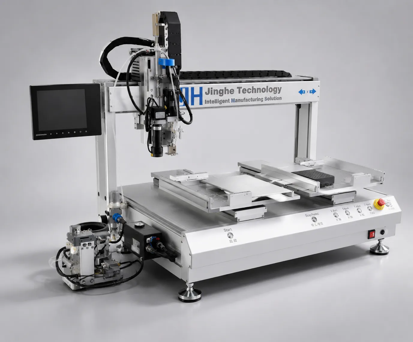 Screw fasteningJHIMS ZM320 Desktop Four-Axis Air-Blowing Screw Fastening MachineDesktop four-axis screw fastening machine using the same controller and blow-type feeding.Open →
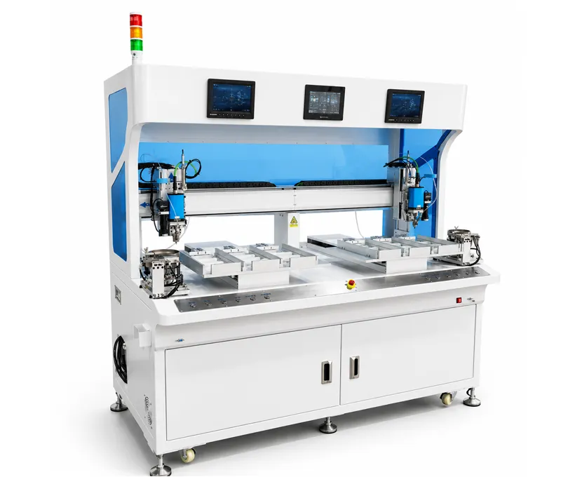 Screw tightening2P-LXS500 High-Speed LED Module Screw Tightening MachineHigh-speed LED module screw tightening platform for higher volume lines.Open →
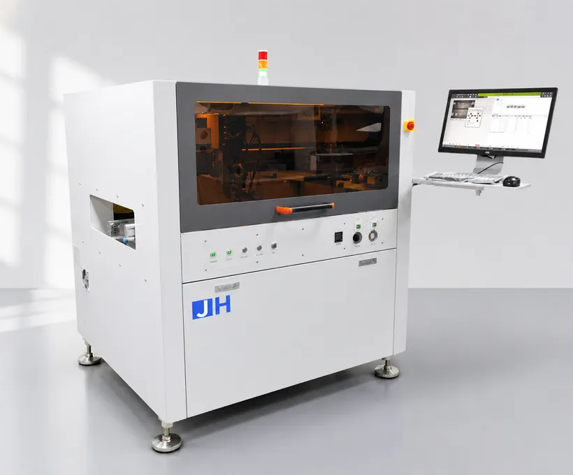 Line companionJH-D900 High-Precision Automatic Glue Dispensing MachineAutomatic glue dispensing machine used alongside fastening on LED module and PCB assembly lines.Open →
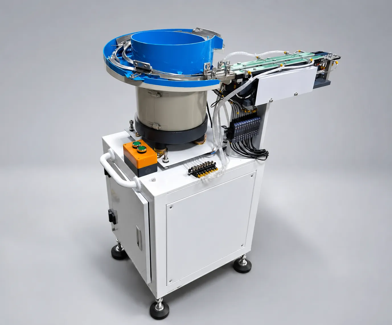 Feeding automationLens Vibratory Feeder DPS-2Automatic lens vibratory bowl feeder for SMT pick-and-place lines.Open →Other guideBL18 Video GuideThe same 19-video training format applied to the BL18 LED display cabinet fastening machine.Open →
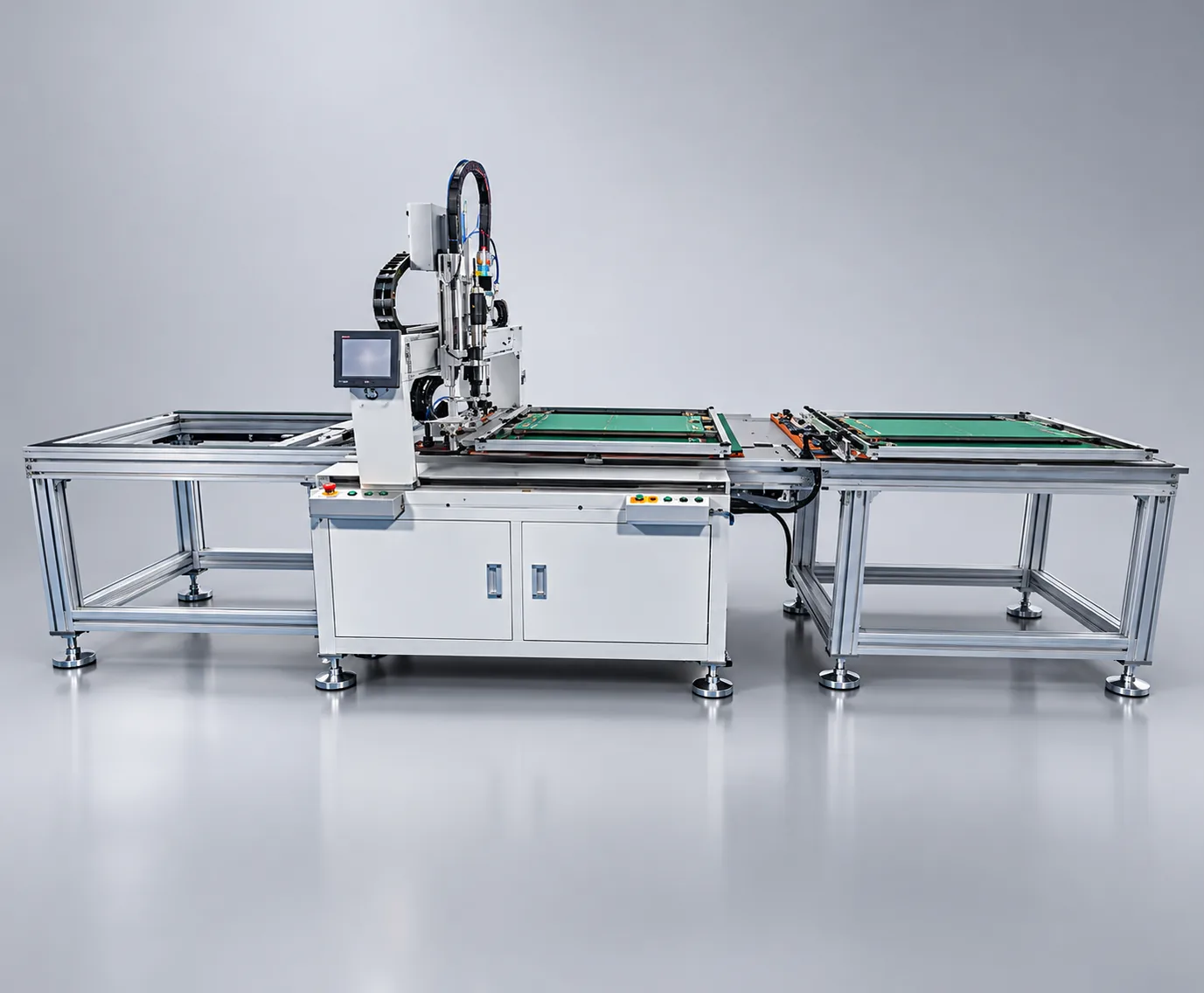 FAQBL18 Troubleshooting FAQ53 symptom-to-video fixes for the BL18 – the same fault-finding method used on this page.Open →
 Other guideR6-U Video GuideThe 19-step video format applied to the R6-U UV laser marking machine.Open →
 Case studySaudi Arabia Case StudyAn LED display maker that replaced hand screwdrivers with an automated screw tightening platform.Open →
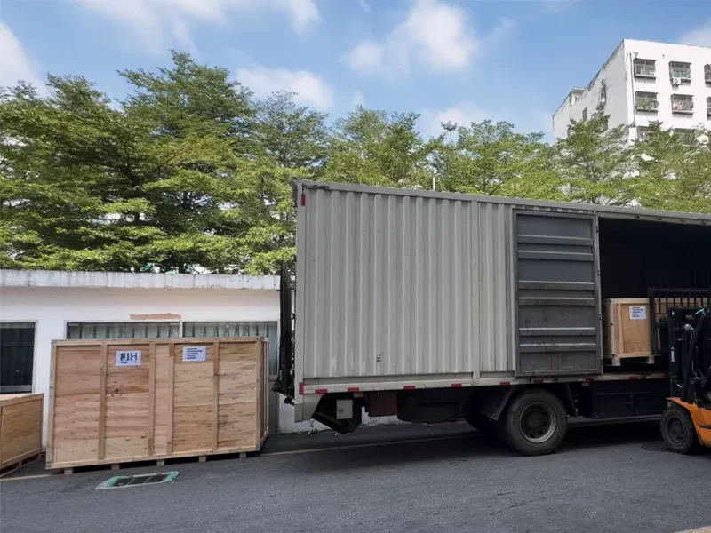 Case studyArgentina InstallationCommissioning and operator training for a cabinet fastening machine in South America.Open →
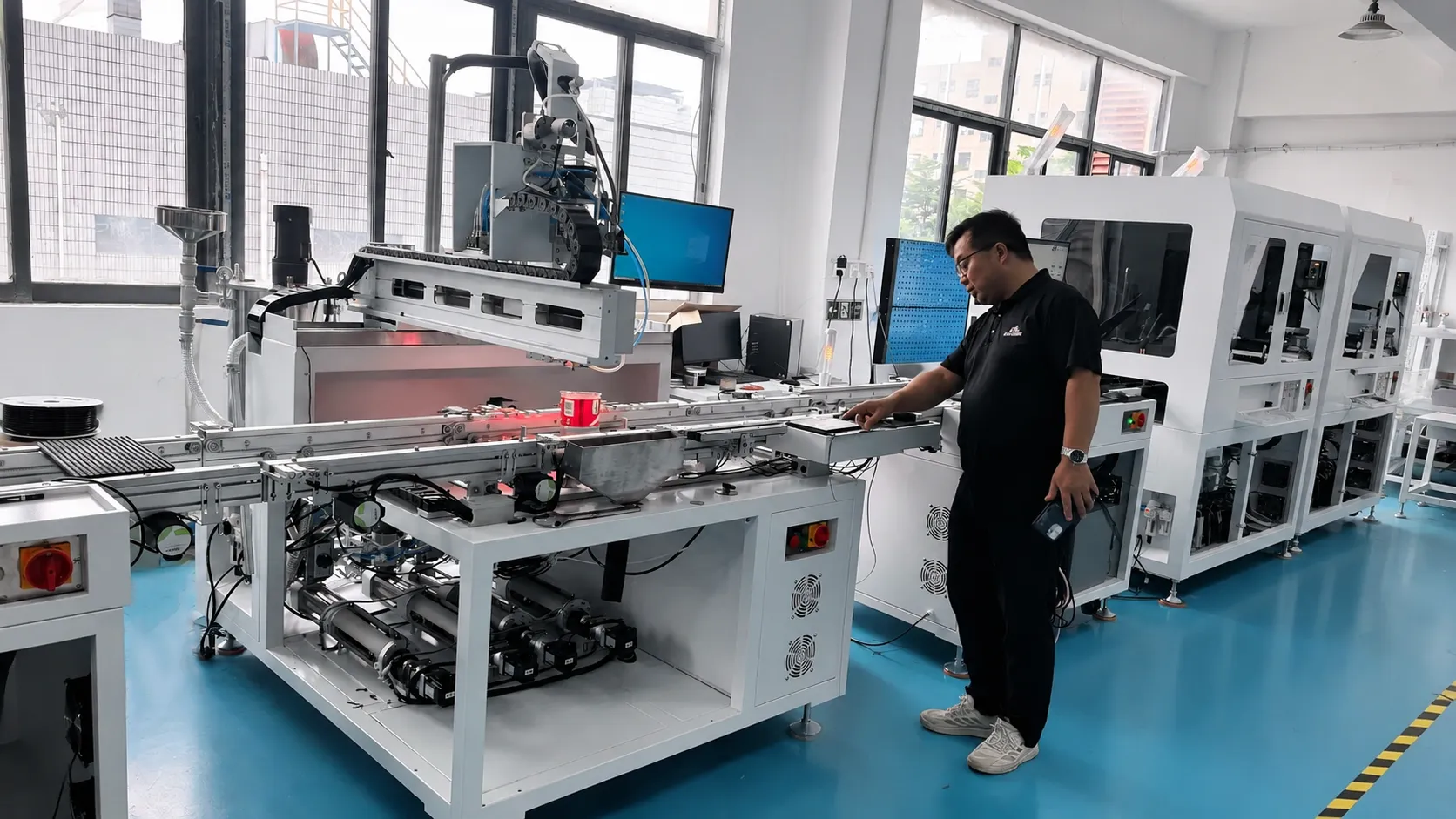 SupportTechnical SupportRemote diagnostics, spare parts and service requests for JHIMS machines.Open →
Send us a photo of the controller screen or the alarm text and the video number you were following – our engineers answer within one business day.