Address
Building A1, Runteng Industrial Park, No. 4 Xishan Road, Longteng Community, Shiyan Subdistrict, Bao'an District, Shenzhen 518000, China
Work Hours
Monday to Saturday: 09:00 – 23:00 (UTC+8)
Sunday: closed
Address
Building A1, Runteng Industrial Park, No. 4 Xishan Road, Longteng Community, Shiyan Subdistrict, Bao'an District, Shenzhen 518000, China
Work Hours
Monday to Saturday: 09:00 – 23:00 (UTC+8)
Sunday: closed

Dual-frequency vs single-frequency vibratory feeding compared on amplitude stability, drift across bowl load, alignment quality and rejection — plus three checks for your own lens.
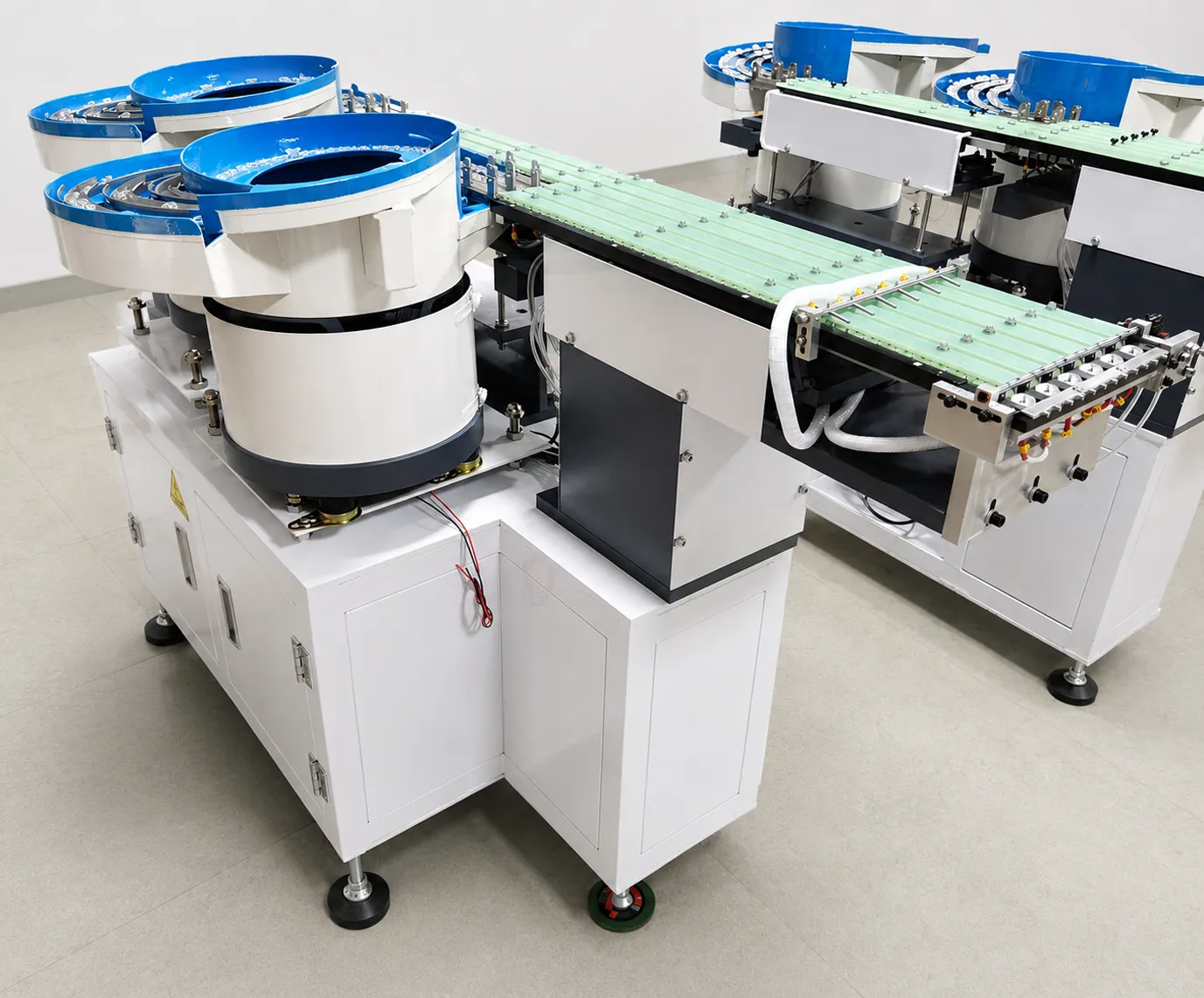
A drive-architecture comparison for SMT lens feeding: why one fixed frequency drifts with bowl load, what two independent PID-controlled channels change, and how to verify amplitude stability on your own lens.
A single-frequency vibratory feeder uses one electromagnetic drive coupled to both the bowl and the track. The drive coil is tuned to a fixed frequency, matched to the resonant frequency of the spring-mass system at a nominal fill level.
The system works well at that nominal load. The limitation appears the moment the load changes.
The practical consequence shows up as a maintenance routine. Because the single coil has to satisfy both the bulk movement in the bowl and the alignment task on the track, the operating point that suits a 50% fill level is already wrong at 100% and at 20%.
Operators learn to compensate with the amplitude dial rather than with tooling: run the bowl high when full, raise it again as lenses thin out, and accept a different part velocity on the track in each state. Nothing in the machine records which setting was used, so the same lens can be fed differently on the morning and night shifts of the same day.
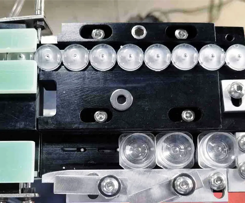
The bowl-and-track assembly is a spring-mass system. Its resonant frequency depends on mass:
But the drive frequency is fixed. As the mass changes through a shift, the system moves away from resonance, mechanical amplification drops, and amplitude falls by 15–30%. Feeding slows, orientation becomes inconsistent, and operators compensate by manually re-tuning the controller every 1–3 hours. This is not a defect that can be “tuned away” — it is inherent to driving two coupled functions from one fixed frequency.
The drift is measurable rather than theoretical. With a fixed drive frequency the mechanical amplification of the spring-mass system falls away from its maximum as soon as mass moves: a bowl that is 80–90% full runs roughly 15–30% lower in amplitude than the tuned state, and the loss is progressive rather than a step change.
On a lens line that shows up first as slower take-up at the track, then as missed pickups, and finally as operators adding lenses by hand to keep the track full — which reintroduces the manual handling the feeder was installed to remove.
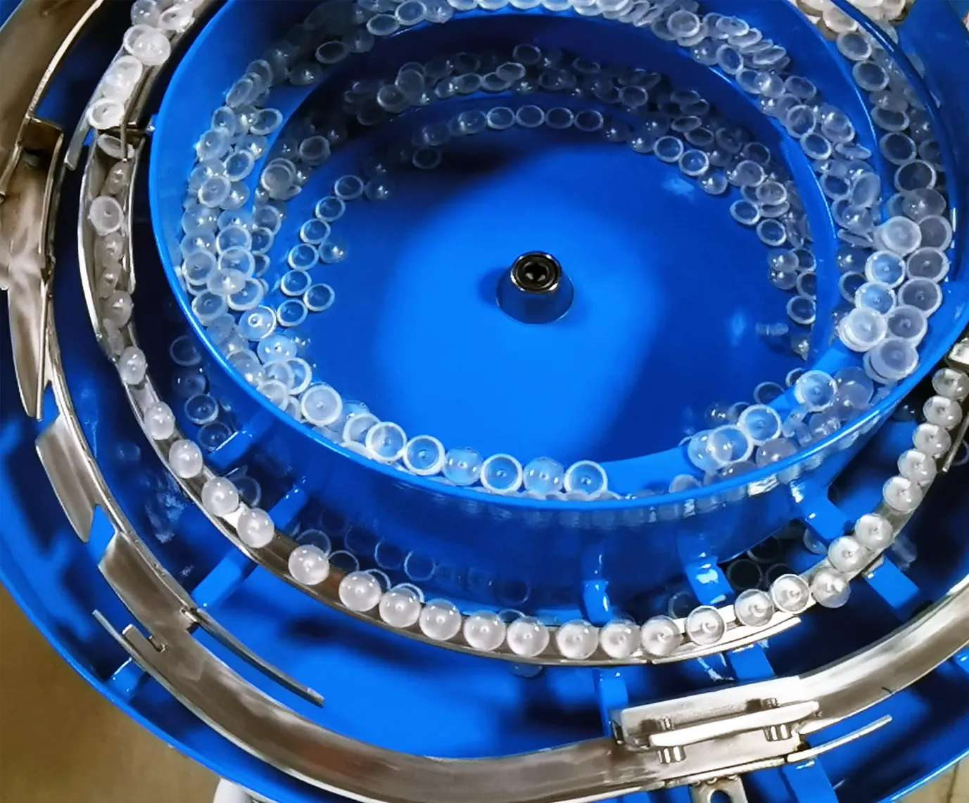
Dual-frequency architecture separates the two feeding functions into independent electromechanical channels:
The drives are mechanically decoupled and electronically independent. Each channel has its own PID controller that continuously measures and adjusts drive power to hold its amplitude setpoint. When the bowl load changes, the circular channel compensates on its own — the alignment track never sees the disturbance.
Decoupling also changes what an operator has to do. The circular channel absorbs the load change on its own, so the linear channel keeps the same amplitude setpoint from a full bowl to an almost empty one; the person running the line changes a recipe, not a dial.
In service that means the feeder can run a full shift without re-tuning, and that a recipe validated at acceptance remains the recipe that produced the accepted rejection rate three months later — which is what makes the numbers in a feeding agreement repeatable.
| Parameter | Single-Frequency | Dual-Frequency |
|---|---|---|
| Drive architecture | One electromagnetic drive, bowl + track coupled | Two independent drives, mechanically decoupled |
| Control | Fixed-frequency open setting | Independent PID loops per drive |
| Resonance sensitivity | High — shifts with bowl load | Low — load disturbance absorbed by bowl loop |
| Amplitude stability | 15–30% variation across fill levels | <5% variation |
| Feeding consistency | ±15–25% speed drift | ±3% speed consistency |
| Operator adjustment | Re-tune every 1–3 hours | Full-shift unattended operation |
| Lens orientation | Degrades as amplitude drifts | Stable at the pickup point |
| Rejection tendency | 2–5% typical | <0.5% |
Read the two columns as two control philosophies rather than two price points. The single-frequency column describes a mechanical system whose behavior is fixed at commissioning and then left to drift with load; the dual-frequency column describes a controlled system whose behavior is held by feedback loops.
For a lens line running one lens for months at moderate volume, the first can be adequate. For mixed, thin or coated lenses where a rejected part costs more than the feeding step itself, the second is the cheaper architecture in total cost of ownership.
Figures reflect typical behavior of the two architectures in SMT lens feeding service; actual values depend on lens geometry and operating conditions.
Vibration architecture is not an abstract design detail — it propagates directly into production outcomes:
For a production manager, the chain ends at one question: can the line run a full shift without someone babysitting the feeder? Single-frequency systems answer it with a schedule of manual re-tuning; dual-frequency systems answer it with control engineering.
Alignment quality is the second half of the argument. Amplitude on the linear channel sets the velocity with which a lens reaches the escapement, and that velocity decides whether the lens arrives flat and centred or slightly rotated.
A drift of a few percent is invisible on a printed part but visible on a lens: the vacuum nozzle meets the optical surface at a small angle instead of squarely. Holding amplitude within ±3% keeps the presentation geometry constant, which is why published rejection figures for dual-frequency lens feeding sit under 0.5% while single-frequency installations typically report 2–5%.
The table below turns the architecture choice into a production decision. It is deliberately written as conditions rather than as a recommendation: match your own line against the left column and read across.
| Production condition | Single-frequency | Dual-frequency |
|---|---|---|
| One lens type, stable volume | workable at nominal fill | stable at any fill level |
| Lens type changes weekly or daily | re-tuning per change | recipe recall per lens |
| Rejection budget below 1% | 2–5% typical | under 0.5% specified |
| Unattended shifts | operator must watch fill level | full-shift unattended |
| Lenses smaller than 5 mm | orientation drifts with amplitude | stable presentation geometry |
| Coated or fragile lenses | impact risk at high fill | gentler bulk channel, separate alignment |
| Multiple lanes in one line | each lane re-tuned separately | independent loops per lane |
| Data reporting to MES | manual logging | Modbus TCP from the PLC |
| Retrofit of an existing bowl | limited improvement | requires new drive architecture |
| Decision horizon | lowest entry cost | lowest total cost of ownership |
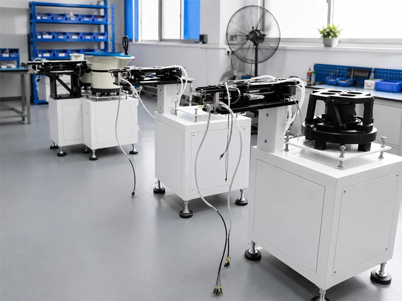
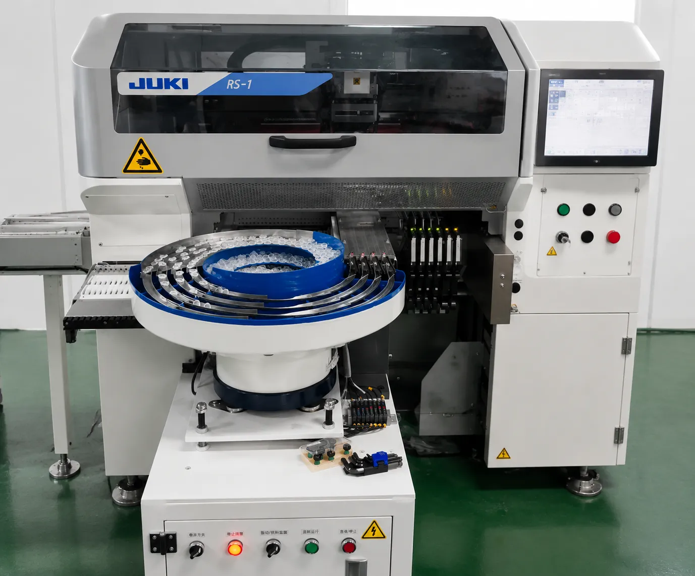
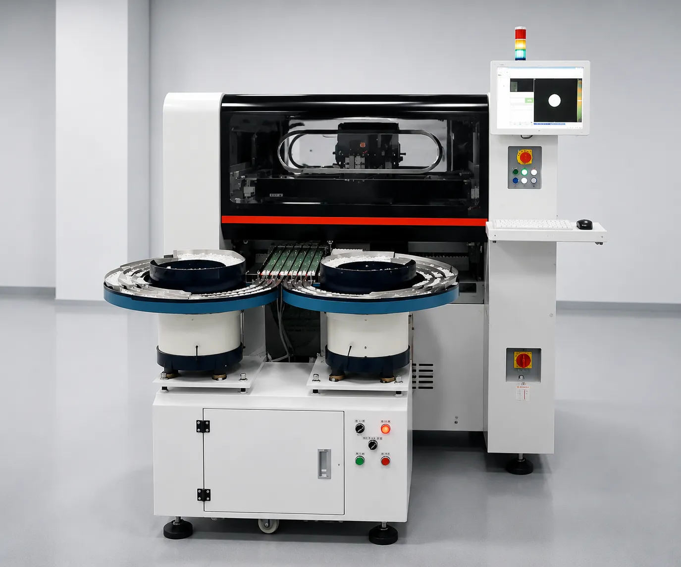
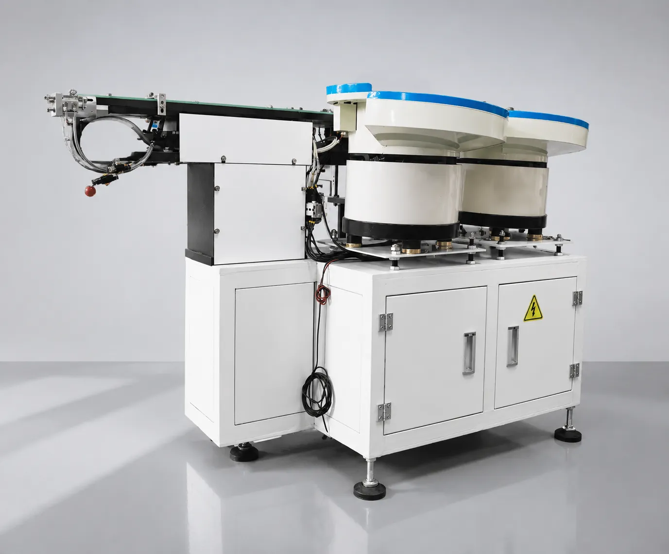
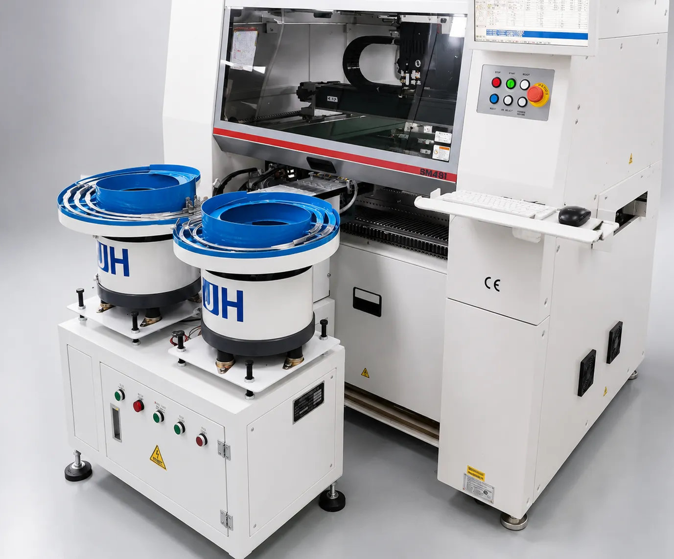
The JHIMS DPS-2 lens vibratory feeder applies this dual-frequency architecture to SMT lens feeding: a 50–120 Hz circular channel for bulk movement and a 100–200 Hz direct channel for precision alignment, each under independent PID control. If you are weighing manual feeding against automation, see the manual vs. automatic decision guide; for fault finding on an installed unit, the DPS-2 troubleshooting guide covers the most common symptoms.
See the architecture in operation: Vibratory Bowl Feeder for SMT Pick and Place — JHIMS on YouTube, or browse more on the official JHIMS YouTube channel. Questions about your lens geometry? Message a JHIMS engineer on WhatsApp.
The same architecture scales to multi-channel configurations: each lane carries its own bowl and linear channel, and each pair runs its own pair of PID loops, so adding a lane does not change the behavior of the lanes already in production. That is what allows a line to add a second lens type without disturbing the acceptance numbers of the first, and it is why the DPS-2 is quoted per channel rather than per machine envelope.

A feeding comparison becomes useful only when it can be checked on your own part. Three checks are enough, and all of them can be run during a sample test without buying anything. First, measure amplitude at three fill levels — full, half and nearly empty — and record the variation; a dual-frequency system should stay within a few percent, while a single-frequency system will move by a double-digit percentage.
Second, run the feeder for a full shift without touching the controller and log rejection; a drift-dependent system shows a rising reject count in the last hours of the shift, the classic symptom of a detuning resonance point. Third, count manual interventions: every time an operator tops up the track by hand or turns an amplitude dial, note it. That count per shift is the clearest single number, because it is the labor the automation was supposed to remove.
We run these checks on customer lenses as part of a free 48-hour sample test with 500–800 lenses, and report amplitude behavior, orientation quality and rejection alongside throughput. If your lens is coated, thin or smaller than 5 mm, ask for the amplitude record at the three fill levels rather than a single figure at nominal load — that is where the architectures separate.
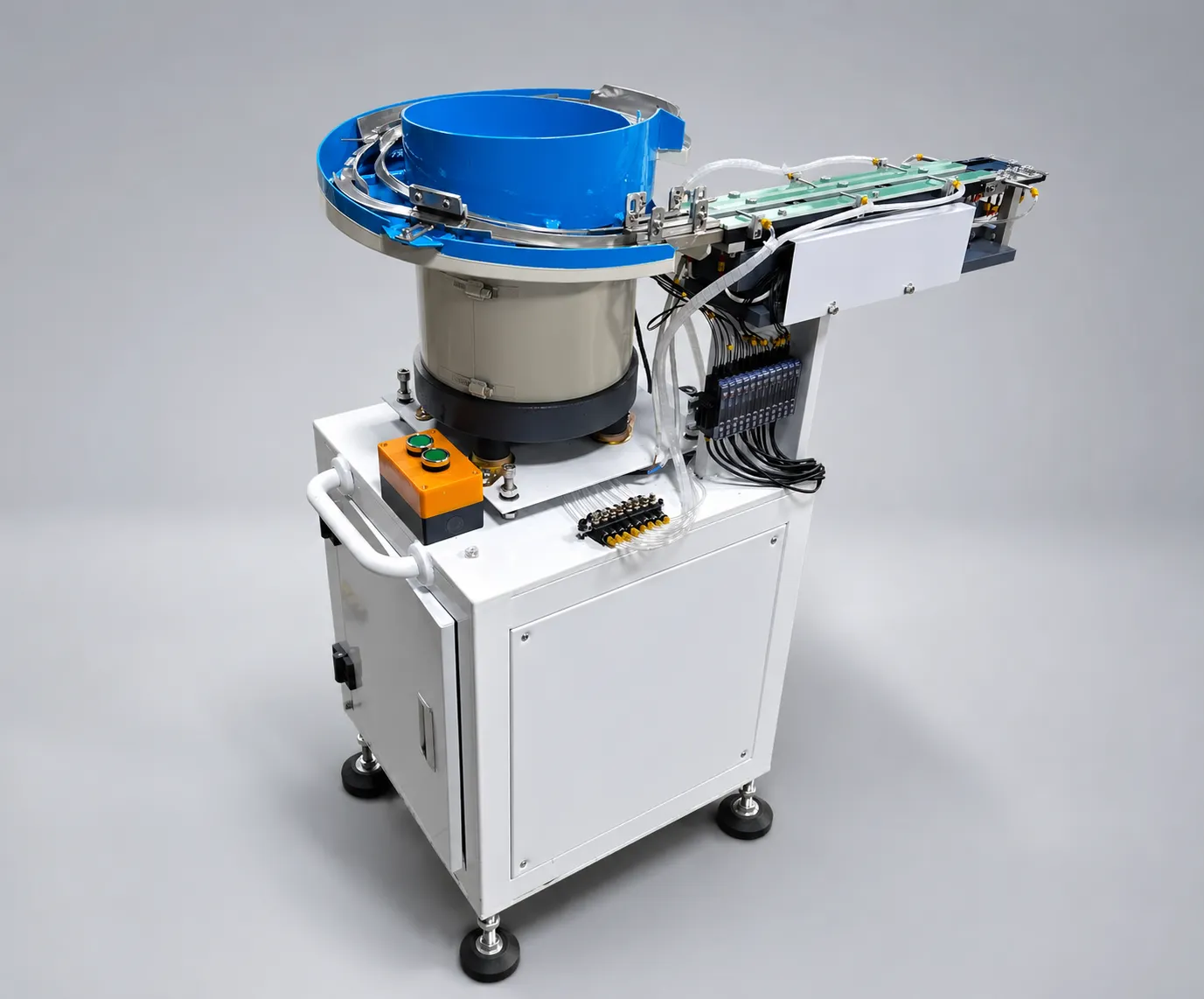 RelatedDPS-2 Full SpecificationsDPS-2 Full SpecificationsView product →
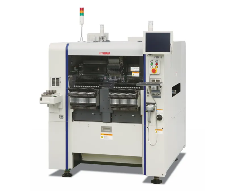 CompanionYamaha YSM10 MounterHigh-speed compact modular mounter – 46,000 CPH, 96 feeders, e-Vision + Side View.View product →
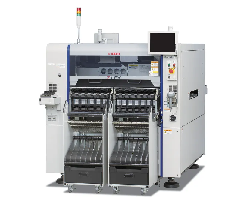 Yamaha YSM20R Pick and Place95,000 CPH modular mounter — pairs with DPS-2 lens feeding lines.View product →
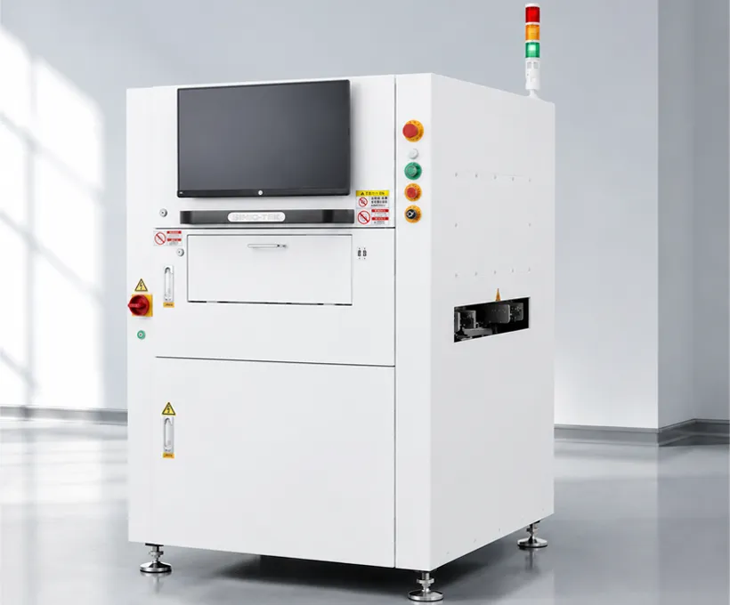 3D SPI Solder Paste InspectionCatch printing defects before reflow with 100% 3D paste inspection.View product →
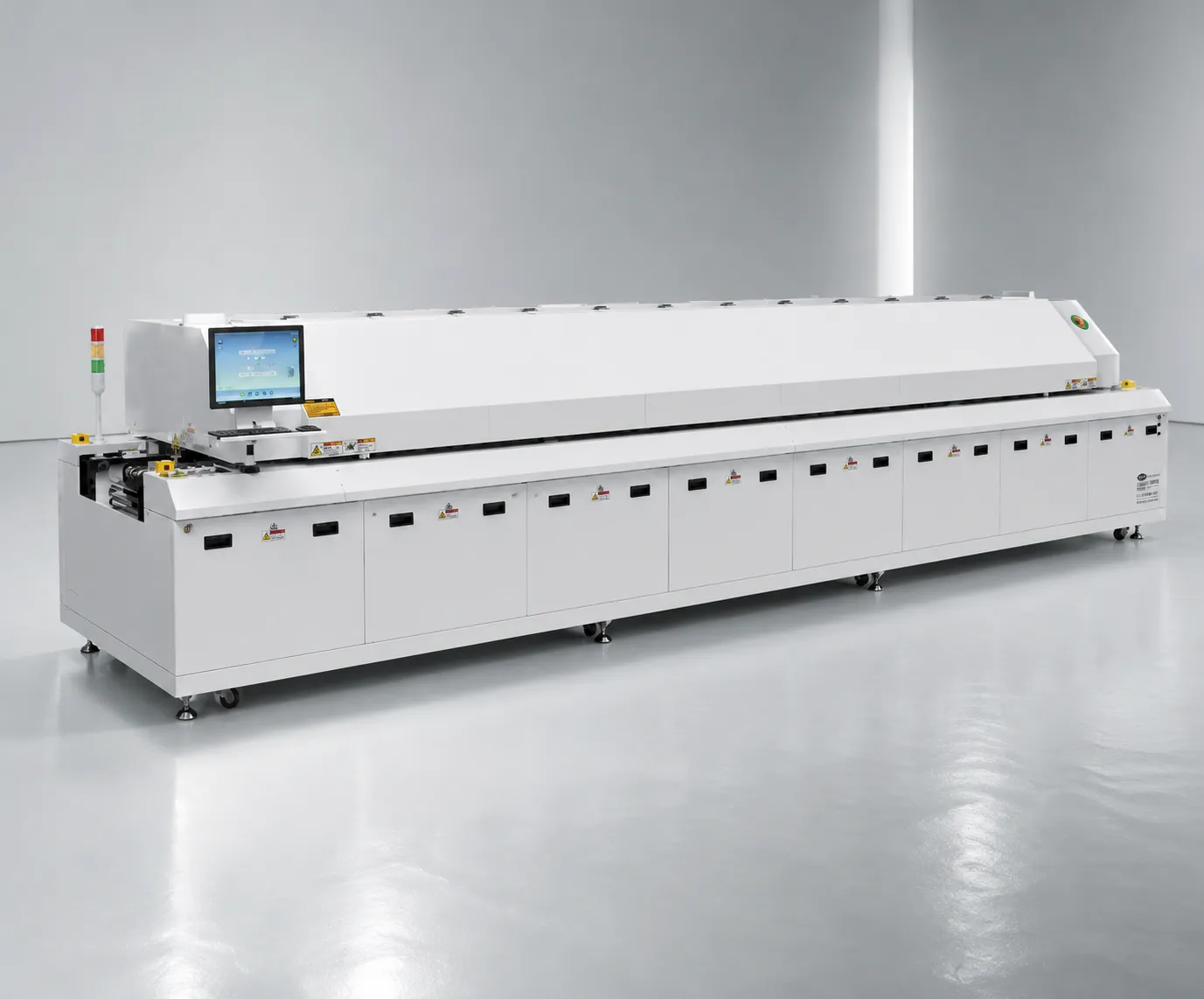 R10 Reflow OvenLead-free hot air reflow with stable thermal profiling for lens assemblies.View product →
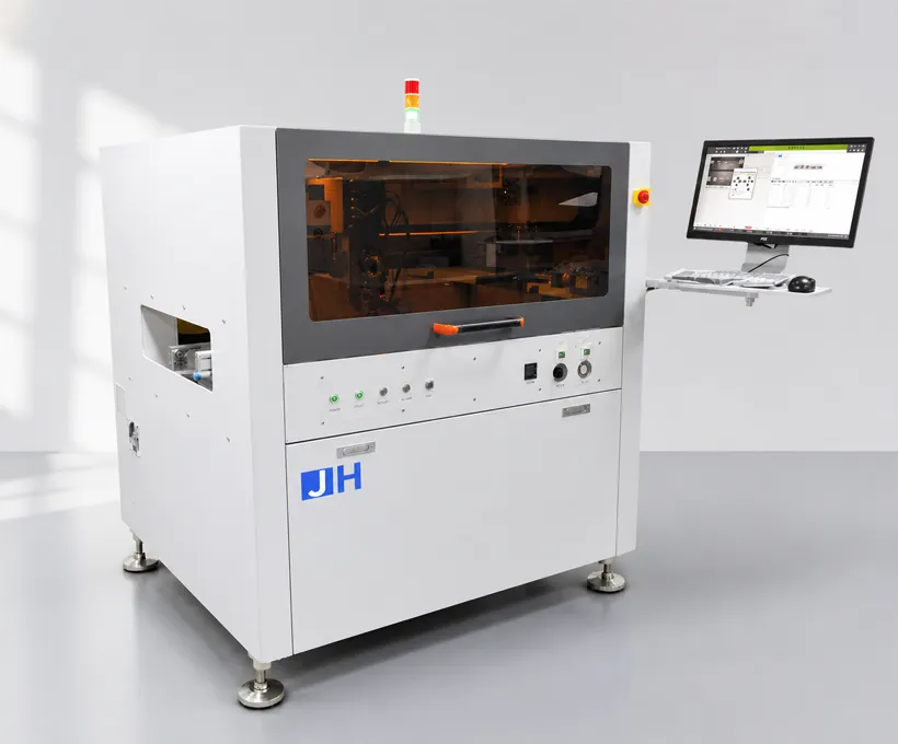 D900 Dispensing MachinePrecision dispensing for conformal coating and lens bonding steps.View product →
 GuideManual vs. Automatic Lens FeedingDecision guide with cost comparison and payback analysis.Read guide →SupportDPS-2 Troubleshooting GuideSymptom → cause → fix procedures for common feeding issues.Read guide →
 FAQDPS-2 FAQ — 40 Buyer QuestionsTechnical, commercial, and after-sales answers in one place.Read FAQ →
 Buying GuideHow to Choose an SMT Lens Feeder (2026)An 8-step buying path, supplier scorecard and dual vs single frequency comparisonRead article →
 Case StudySMT Lens Feeder ROI Case StudyReal KPI transition: defect rate 12%→0.3%, UPH 900→3420, 7-month paybackRead article →
 GlossarySMT Lens Feeding GlossaryTerminology for vibratory feeding, PID control, and UPH metrics.Read glossary →
Send us your lens diameter, shape, and target UPH — our engineers will evaluate whether dual-frequency feeding fits your line, with a free evaluation, first reply within 12 working hours (Mon–Sat, 09:00–23:00 China Standard Time, UTC+8).