Address
Building A1, Runteng Industrial Park, No. 4 Xishan Road, Longteng Community, Shiyan Subdistrict, Bao'an District, Shenzhen 518000, China
Work Hours
Monday to Saturday: 09:00 – 23:00 (UTC+8)
Sunday: closed
Address
Building A1, Runteng Industrial Park, No. 4 Xishan Road, Longteng Community, Shiyan Subdistrict, Bao'an District, Shenzhen 518000, China
Work Hours
Monday to Saturday: 09:00 – 23:00 (UTC+8)
Sunday: closed

How a 12-line TV backlight plant moved from hand-placed lenses to 24 DPS-2 feeders: rejection 12% to 0.3%, throughput 900 to 3,420 UPH, OEE 58% to 81%, payback in 7 months.
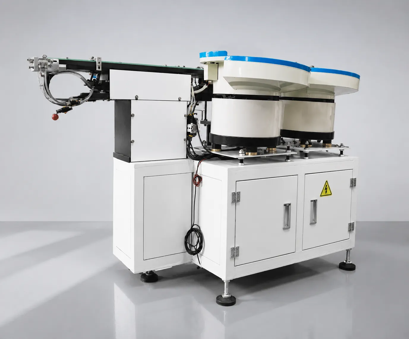
How a 12-line TV backlight plant moved from hand-placed lenses to 24 DPS-2 feeders: the measured baseline, the acceptance criteria, and the KPI transition that produced a 7-month payback.
This lens feeder ROI case study covers a 12-line TV backlight operation in Qingdao. At a glance:
Treat the at-a-glance block as the project’s constraint set, not background. Twelve SMT lines running 24/7 in peak season means feeding fails as a system: one underperforming line starves those downstream, and a 30-minute changeover costs that time twelve times over. Annual TV volume implies continuous, large lens demand, which is why the manual station became the binding constraint. The customer is a major electronics brand kept confidential here: no company or personal names are published, while the engineering data is reported in full.
The customer produces over 20 million TV units annually. Its Qingdao factory operates 12 SMT lines for TV backlight module assembly, running 24/7 during peak seasons. Backlight lenses were placed onto light bars by hand: operators picked each lens and positioned it manually before reflow.
Manual lens feeding is one of the most labor-intensive steps in backlight module production, and the lens feeder decision became a bottleneck for the whole factory. The manual process scaled poorly: as volumes grew and TV backlight designs moved to thinner, more varied lens geometries, it became the weakest link in the line. It limited throughput, produced inconsistent placement quality, and made peak-season staffing a constant problem.
The cause was geometry. As light bars became thinner and lens outlines more varied, the manual nest that worked for the previous generation got harder to hit: the lens is small, the placement window narrow, and the operator positions by eye at the rate the line demands every shift. Handling between tray and nest adds contamination and misorientation as separate defect sources, and rejection widens with fatigue — so the line was planned around its worst hours. The answer is to take the operator out of the orientation step.
Four problems pushed the customer to automate lens feeding — all measurable, all costing production time:
Each challenge has a cost mechanism worth stating, because the mechanisms are what a solution must interrupt. A 12% rejection rate is not only scrapped lenses: every rejected module also carries its consumed material, the labor to detect and rework it, and inspection capacity. A feeding rate of about 900 UPH means the placement machine waits between cycles, so downstream equipment runs under-loaded and managers compensate with overtime rather than capacity. Changeovers of 30 minutes across twelve lines add production hours that never appear on a defect report.
The customer’s purchasing team set five measurable requirements before evaluating any lens feeder supplier:
The five requirements were written so each could be measured on the live line rather than argued about afterwards: throughput as a feeding rate that stops starving the placement machines; quality as rejection far below the 12% baseline without extra inspection labor; flexibility as changeover across several lens geometries; automation as one operator per line or fewer; and certainty as validation on the customer’s own lenses before shipment — which turned the project into an acceptance procedure rather than a specification exercise.
The project was accepted against measured line data, so the first task was to fix the baseline honestly. Before any feeder was installed, four KPIs were recorded from the customer’s own systems: rejection 12%, feeding throughput about 900 UPH per line, operator deployment at manual levels per line, and OEE 58%. Writing those numbers down before the project starts is what makes a later comparison legitimate — a baseline reconstructed afterwards tends to move in whichever direction the discussion requires.
The second step bound the numbers to the equipment. A feeding rate of 0.5 to 1 second per lens per channel equals 3,600 to 7,200 UPH per channel, the figure the configuration has to deliver on the actual lens set; rejection below 0.5% is the quality figure the tooling has to reach on those same lenses. Because the burn-in ran 48 hours on the customer’s production lenses, the acceptance values and the shipping values came from the same parts, and acceptance ran on live production with all four KPIs measured simultaneously.
The baseline was recorded before installation and used as the reference for acceptance. Each line below states where the number comes from, so the same method can be applied on another line.
| Baseline item | Value recorded before installation | Source of the measurement |
|---|---|---|
| Rejection rate | 12% from manual lens placement | Line quality records at the defined counting point |
| Feeding throughput | About 900 UPH per line | Placement machine counters over a full shift |
| Operator deployment | Manual placement staffing on every line | Staffing roster and line manning plan |
| OEE | 58% | Line throughput and stop-time data |
| Changeover time | 30 minutes or more per lens change | Production log for setup events |
| Equipment scale | 24 DPS-2 units, 2 per line, 4-channel configuration | Project configuration list |
| Validation basis | Customer production lenses, 48-hour burn-in before shipment | Pre-shipment test report |
| Acceptance window | 30-day acceptance on live production | Contract acceptance clause |
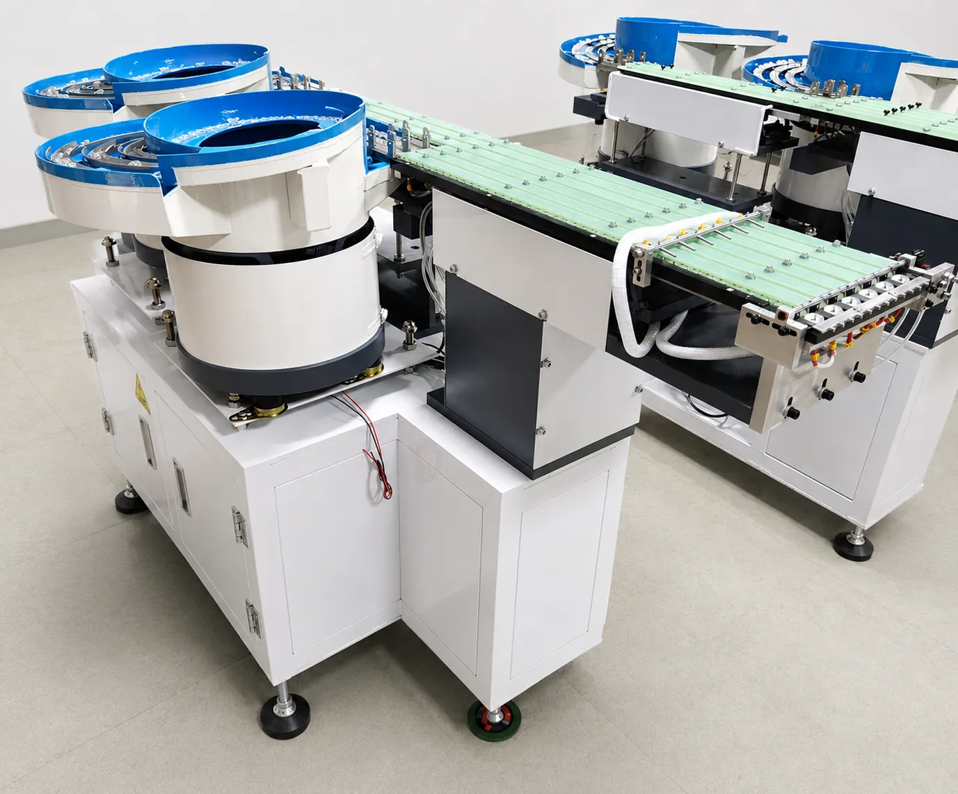
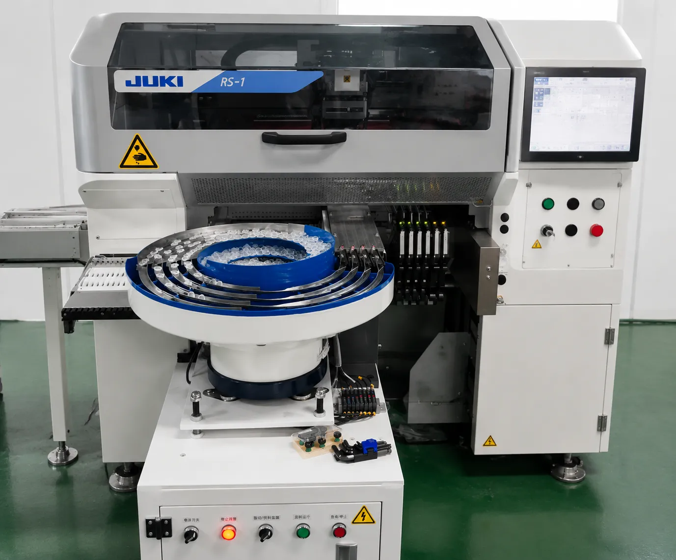
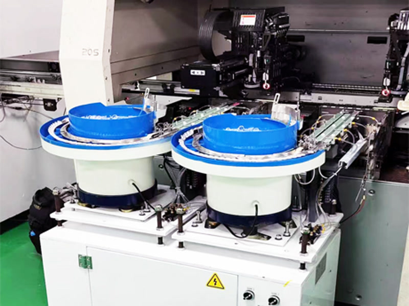
JHIMS deployed 24 DPS-2 lens vibratory feeders (2 per line) with custom 4-channel configurations matched to the customer’s backlight lens geometries. Each unit feeds lenses directly to the placement head at 0.5–1 second per lens with a rejection rate below 0.5%, driven by patented dual-frequency vibration technology.
The dual-frequency architecture separates bulk circular feeding from precision linear alignment — eliminating the resonance interference common in single-frequency feeders and keeping amplitude stable across load changes. PLC preset profiles stored complete vibration parameters: up to 50 lens-type presets made changeover tool-less and under 5 minutes, with profile recall fast enough to cut setup time by up to 80%.
Before shipment, all 24 units ran a 48-hour burn-in test at the JHIMS Shenzhen facility using the customer’s actual production lenses — the same validation JHIMS offers every buyer through its free 48-hour sample feeding test.
The full feeding setup deployed per line:
| Item | Configuration |
|---|---|
| Equipment | JHIMS DPS-2 lens vibratory feeder (24 units total) |
| Deployment | 2 units per line × 12 SMT lines |
| Channel setup | Custom 4-channel configuration per lens geometry |
| Feed rate | 0.5–1s per lens — 3,600–7,200 UPH per channel |
| Lens range | 3–25mm — inner/outer three-feet and four-angle reflection types |
| Vibration technology | Patented dual-frequency (circular + direct vibration) |
| Control | Fully automatic PLC with HMI touchscreen, up to 50 preset profiles |
| Alignment tolerance | ±1mm (based on lens shape and pin dimensions) |
| Pre-shipment validation | 48-hour burn-in with the customer’s actual lenses |
Two units per line was a capacity decision, not redundancy. The line runs a mixed lens set, and channel count was chosen so the feeder exceeds the placement machine’s lens consumption with headroom for changeover and for re-tooling one channel. Four channels per unit also helps on a high-mix schedule: one channel can be offline for tooling while the others keep feeding, so a lens change becomes a sequence of lane changes instead of a stop. Alignment tolerance was set at plus or minus 1 mm from lens shape and pin dimensions.
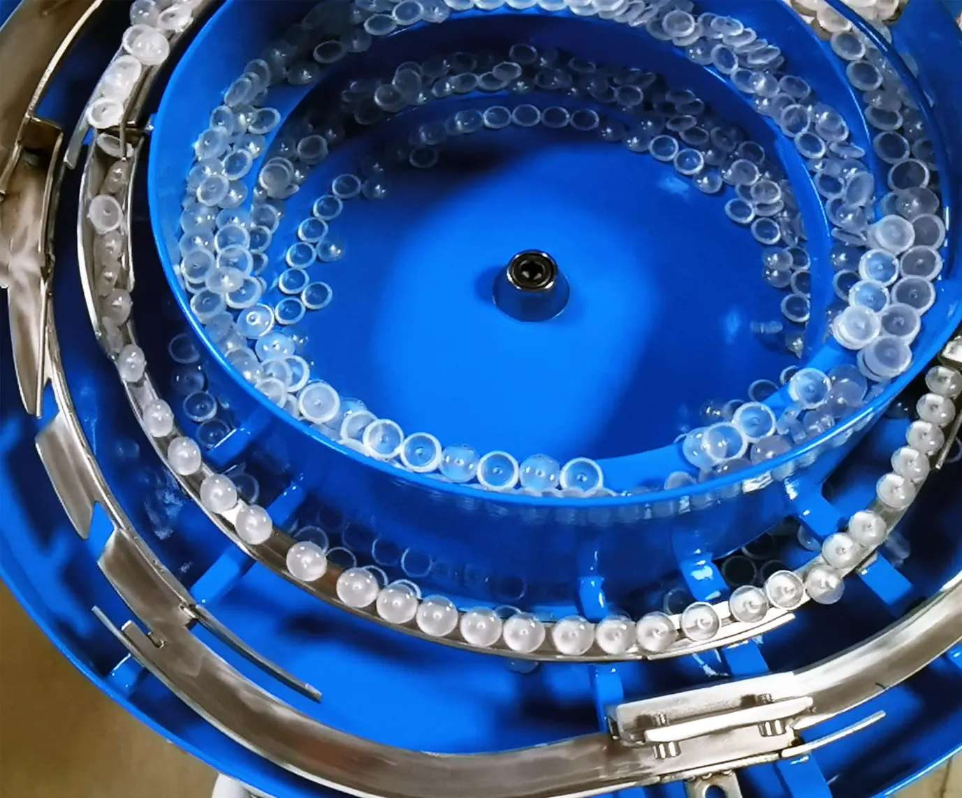
The rollout followed a five-phase path designed to remove risk at every step — from sample validation to full production:
| Phase | What Happened | Benefit |
|---|---|---|
| 1. Sample validation | Customer lenses run through a 48-hour feeding test; measured rejection and amplitude reported | Performance proven on the customer’s own product before any commitment |
| 2. Engineering & burn-in | Custom 4-channel configurations built; 48-hour burn-in at JHIMS Shenzhen with actual lenses | Every unit validated before shipment — no surprises at commissioning |
| 3. Installation & commissioning | 2 units per line installed; PLC preset profiles loaded for each lens geometry; operator training | Lines back in production quickly, changeover ready from day one |
| 4. 30-day acceptance | KPIs verified on live production: rejection, UPH, operators, OEE | Contractual acceptance tied to measured results |
| 5. Scale & support | Full 12-line rollout; under 4-hour response and under 48-hour spare parts dispatch | Continuous support through the 1-year warranty and beyond |
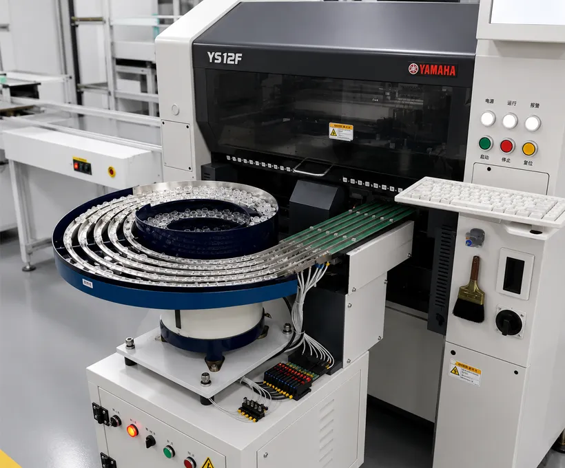
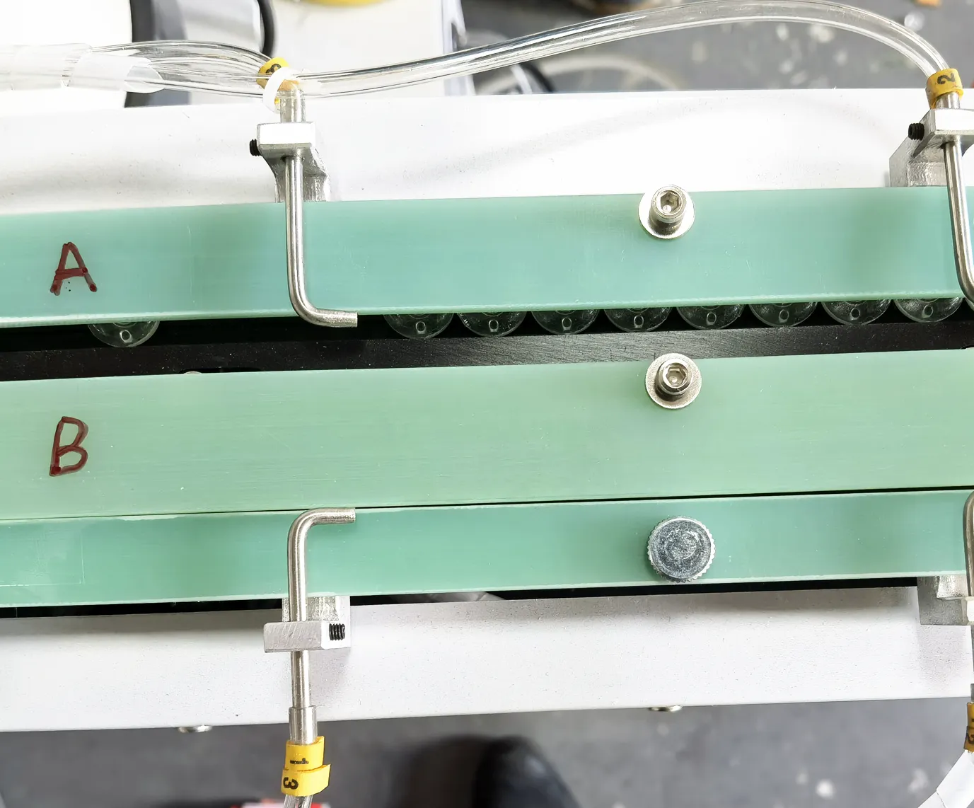
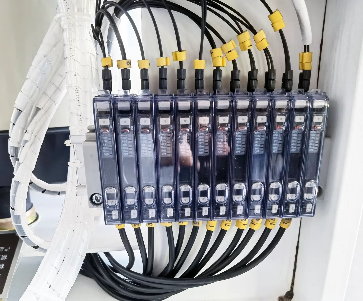
Every KPI in this lens feeder ROI case study was measured on the customer’s live production line after commissioning. The JHIMS DPS-2 ROI result: full payback in 7 months.
| KPI | Before (Manual) | After (DPS-2) | Improvement |
|---|---|---|---|
| Rejection Rate | 12% | 0.3% | 40x reduction |
| UPH per Line | ~900 | 3,420 | 280% increase |
| Operators | Manual (per line) | 1 per 3 lines | Automated control |
| OEE | 58% | 81% | +23 points |
| ROI | — | 7 months | Full payback |
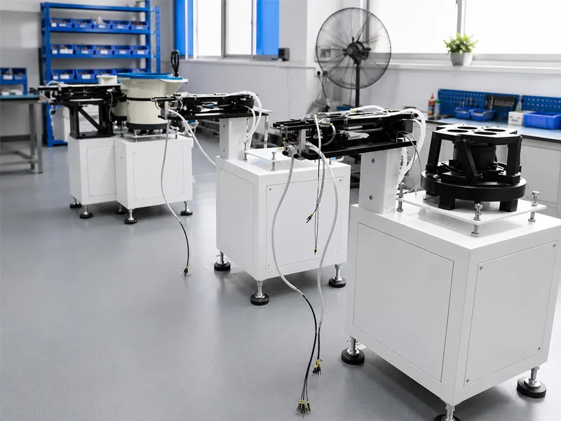
The headline transition: rejection from 12% to 0.3% (about forty-fold), throughput per line from about 900 to 3,420 UPH, OEE from 58% to 81%, staffing at one operator per three lines, and payback in seven months on 24 units. Three effects explain it: variance removal (orientation stopped being a human judgement, so rejection fell and stopped drifting with shift and fatigue), capacity release (placement machines now run at their own rating), and labor release (one operator covers three lines instead of one station).
The payback follows from those effects and from scale: 24 units across 12 lines means the investment is made once per line pair while the savings accrue per line every shift — labor released, material no longer scrapped at 12%, and capacity that would otherwise need overtime. Before expecting a similar result, check three preconditions this customer met: a baseline measurable from existing records, lens geometry inside the 3–25 mm tooling band with a defined orientation requirement, and a changeover frequency high enough that setup time is a real cost.
The four business KPIs and the two equipment figures were all measured on the same production lines, before and after commissioning.
| Metric | Before | After | How it is measured |
|---|---|---|---|
| Rejection rate | 12% | 0.3% | Quality records at the counting point after feeding and placement |
| Feeding throughput per line | About 900 UPH | 3,420 UPH | Placement machine counters over a full shift |
| Operators | Manual placement on each line | 1 per 3 production lines | Staffing roster after automation |
| OEE | 58% | 81% | Line throughput against stop-time data |
| Lens change | 30 minutes or more | Under 5 minutes with PLC recipes | Timed changeover, tooling plus recipe recall and verification |
| Feed rate per channel | Not applicable to manual feeding | 0.5–1 second per lens | Track sensing count per channel over a shift |
| Channels per unit | Not applicable | 4 channels per unit, 2 units per line | Configuration list confirmed at commissioning |
| Alignment tolerance | Placed by eye at the nest | ±1 mm, set from lens shape and pin dimensions | Set-up sheet and pick-up point inspection |
| Recipes in the control | None | Up to 50 lens-type presets in the PLC | Profile list on the HMI |
See the same feeding technology running with real lenses — the technology behind this case study:

Watch the full video on YouTube · more machine and factory videos on the JHIMS official channel.
Watch with one question in mind: how does the lens get from a bulk bowl to a repeatable present position without an operator touching it? The interesting part is not the bowl but the boundary between bulk movement and alignment — circular vibration moves parts in the bowl, and a separate linear stage arranges them along the track at a controlled pitch so the nozzle meets each lens in the same place. That separation is why amplitude can be tuned for the lens rather than for transport.
The Feeder in This CaseJHIMS DPS-2Lens vibratory feeder for SMT pick-and-place · 0.5–1s per lens · <0.5% rejection · ±1mm alignment · 6 P&P brandsView product →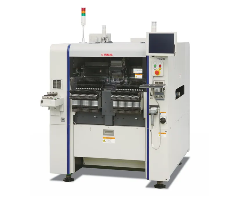 CompanionYamaha YSM10 MounterHigh-speed compact modular mounter – 46,000 CPH, 96 feeders, e-Vision + Side View.View product →
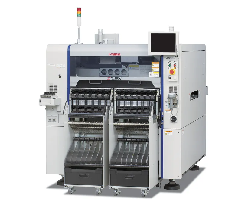 Yamaha YSM20R Pick and Place95,000 CPH modular mounter — pairs with DPS-2 lens feeding lines.View product →
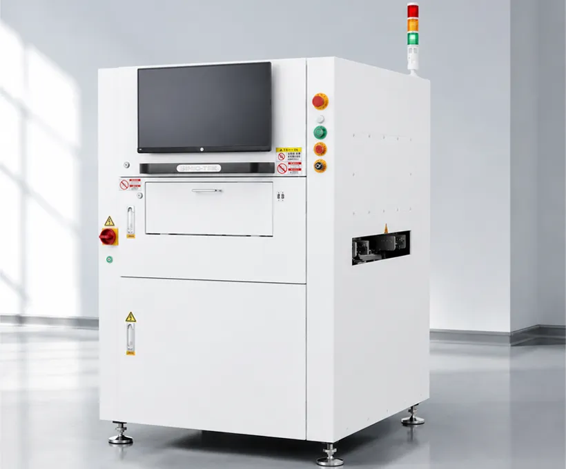 3D SPI Solder Paste InspectionCatch printing defects before reflow with 100% 3D paste inspection.View product →
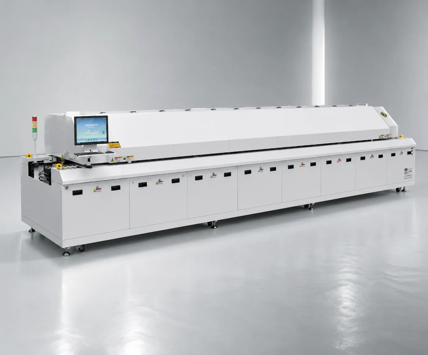 R10 Reflow OvenLead-free hot air reflow with stable thermal profiling for lens assemblies.View product →
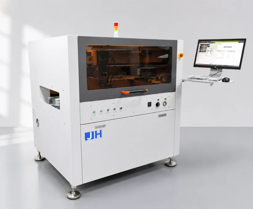 D900 Dispensing MachinePrecision dispensing for conformal coating and lens bonding steps.View product →
 Buying GuideHow to Choose an SMT Lens Feeder (2026)An 8-step buying path, supplier scorecard and dual vs single frequency comparisonRead article →
 ComparisonDual vs Single Frequency Vibratory FeederTechnical comparison of the two vibration technologiesRead article →
 ComparisonManual vs Automatic SMT Lens FeederWhich feeding method is right for your production?Read article →
 Case StudySMT Lens Feeder Case: TV Backlight in XiamenLens feeder deployment on TV backlight production linesRead article →
 Case StudyLens Vibrating Feeder Case: LED Lighting in RussiaVibrating feeder case study in LED lighting productionRead article →
 Buying GuideSourcing SMT Equipment from ChinaA risk-managed procurement guide: supplier verification, scorecards and payment protectionRead article →
Send lens samples for a free 48-hour feeding test and get a customized ROI projection — measured on your lenses, not estimated from a brochure.