Address
Building A1, Runteng Industrial Park, No. 4 Xishan Road, Longteng Community, Shiyan Subdistrict, Bao'an District, Shenzhen 518000, China
Work Hours
Monday to Saturday: 09:00 – 23:00 (UTC+8)
Sunday: closed
Address
Building A1, Runteng Industrial Park, No. 4 Xishan Road, Longteng Community, Shiyan Subdistrict, Bao'an District, Shenzhen 518000, China
Work Hours
Monday to Saturday: 09:00 – 23:00 (UTC+8)
Sunday: closed

Toyota-audit lens feeding case study in Vietnam: a custom DPS-2 feeder for LED lens assembly — jams eliminated, 30% faster feeding and 15% lower cost on a Samsung SLM120S line.
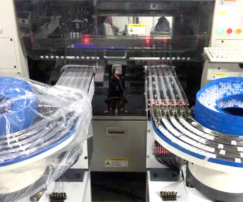
How a Vietnamese LED lighting manufacturer removed lens jamming from its Samsung SLM120S line with a custom JHIMS DPS-2 lens vibratory feeder — one feeder covering every lens in the portfolio, 30% faster feeding and a 15% cost reduction.
At a glance: who the customer is, what they assemble, and what drove the investment.
LED lens assembly is one of the harder feeding duties in electronics manufacturing. The lenses are optically clear and often thin, so they cannot be pushed against hard tooling without risking scratches; the outline is usually a three-foot or four-angle geometry rather than a plain disc, so orientation matters in two axes rather than one.
A lighting product family also changes lens quickly, so the feeding step must support several parts without a mechanical rebuild. Add the volume requirement of a lighting line — tens of thousands of lenses a day — and manual picking becomes the bottleneck the customer set out to remove.
A Vietnamese LED lighting manufacturer struggled with inefficiencies in its lens assembly process. Before the JHIMS lens vibrating feeder was installed, lens jamming disrupted production flow, slow feeding speeds limited output, and the equipment could not accommodate the multiple lens types in the portfolio.
As LED lighting product lines diversified, the manufacturer needed a lens vibrating feeder that could handle its full lens range reliably — without jams and without separate setups for each lens type.
The cost of the old method was not only speed. Every jam stopped the pick-and-place machine and had to be cleared by hand before the line could restart, which meant one operator effectively assigned to watching the feeder for a whole shift. Slow feeding reduced output below what the assembly process could absorb.
Because each lens size and shape needed its own setup, a lens change meant stopping the line to re-adjust vibration and tooling. Those three symptoms — stops, output ceiling and lost changeover time — are the same three that appear in most lens feeding projects.
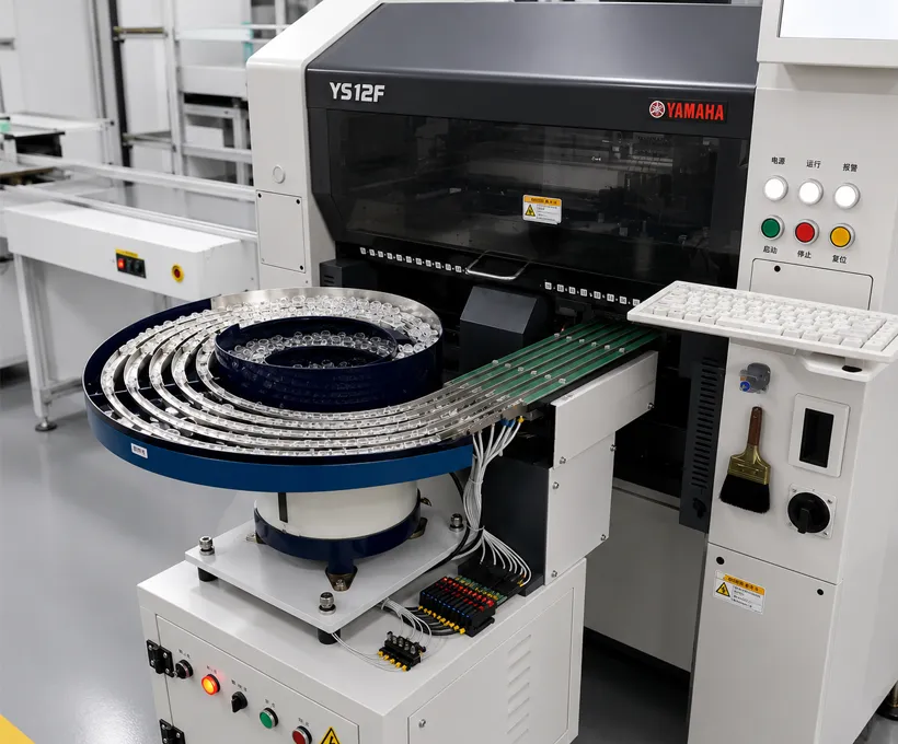
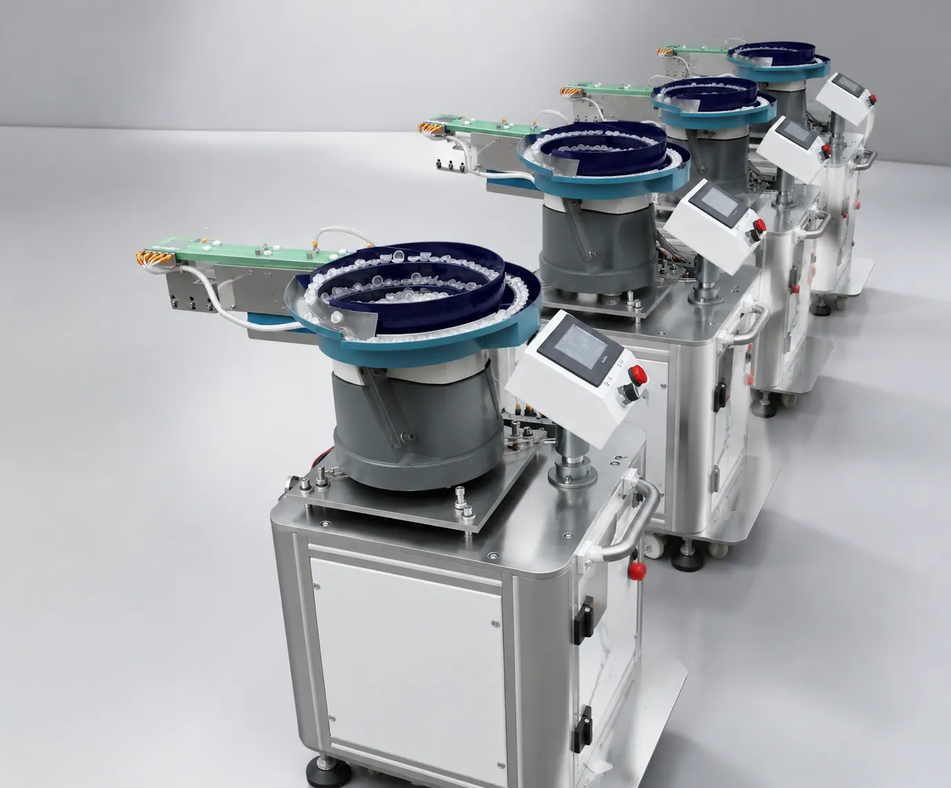
Each of the three challenges has an engineering cause worth naming, because the fix follows from it. Jamming in a circular bowl usually comes from two lenses competing for the same track position at the same moment, which happens when part velocity varies with bowl load.
Slow feeding is the same problem from the other side: reducing amplitude to avoid jams also reduces throughput, so the line runs at the setting with fewest stoppages rather than the fastest safe rate. Multi-lens incompatibility is a tooling problem — track width, escapement geometry and sensor position are all lens-specific.
The three reported challenges mapped to their engineering cause and the design response used in this project.
| Reported challenge | Engineering cause | Design response |
|---|---|---|
| Lens jamming | Part velocity varies with bowl load; lenses compete for the same track position | Dual-frequency drives: bowl absorbs load, linear channel holds presentation |
| Constant operator intervention | Jams had to be cleared by hand before the line could restart | Jam-free transfer removes the intervention, not just the symptom |
| Slow feeding speeds | Amplitude reduced to avoid jams, so throughput ran below the line capability | Independent alignment channel allows full speed at the escapement |
| Multiple lens sizes | Track width, escapement and sensing are lens-specific | Custom routes and wheel spokes covering the whole portfolio |
| Multiple lens shapes | Three-foot and four-angle outlines need orientation in two axes | Orientation tooling verified on the customer’s own parts |
| Setup per lens type | Manual re-adjustment of vibration and tooling at each change | Stored controller settings recalled by lens type |
| Integration with existing line | Feeder had to suit an existing Samsung SLM120S head and nozzle | Standalone control cabinet, head-specific mounting bracket, no machine modification |
The four requirements became the project’s acceptance criteria, which is why they are worth restating as measurable conditions rather than wishes. Jam-free operation was interpreted as no unplanned stops attributable to feeding across the burn-in run; higher speed as a feeding rate that no longer limited line output.
Single-feeder flexibility meant proven change between all the customer’s lens types without replacing tooling, and machine compatibility meant physical and electrical integration with the existing Samsung SLM120S head using the customer’s own nozzle. Writing requirements this way lets both sides agree on what has been demonstrated before the machine ships.
JHIMS engineered a custom lens vibrating feeder for the customer’s Samsung SLM120S pick-and-place machine, leveraging advanced vibration technology:
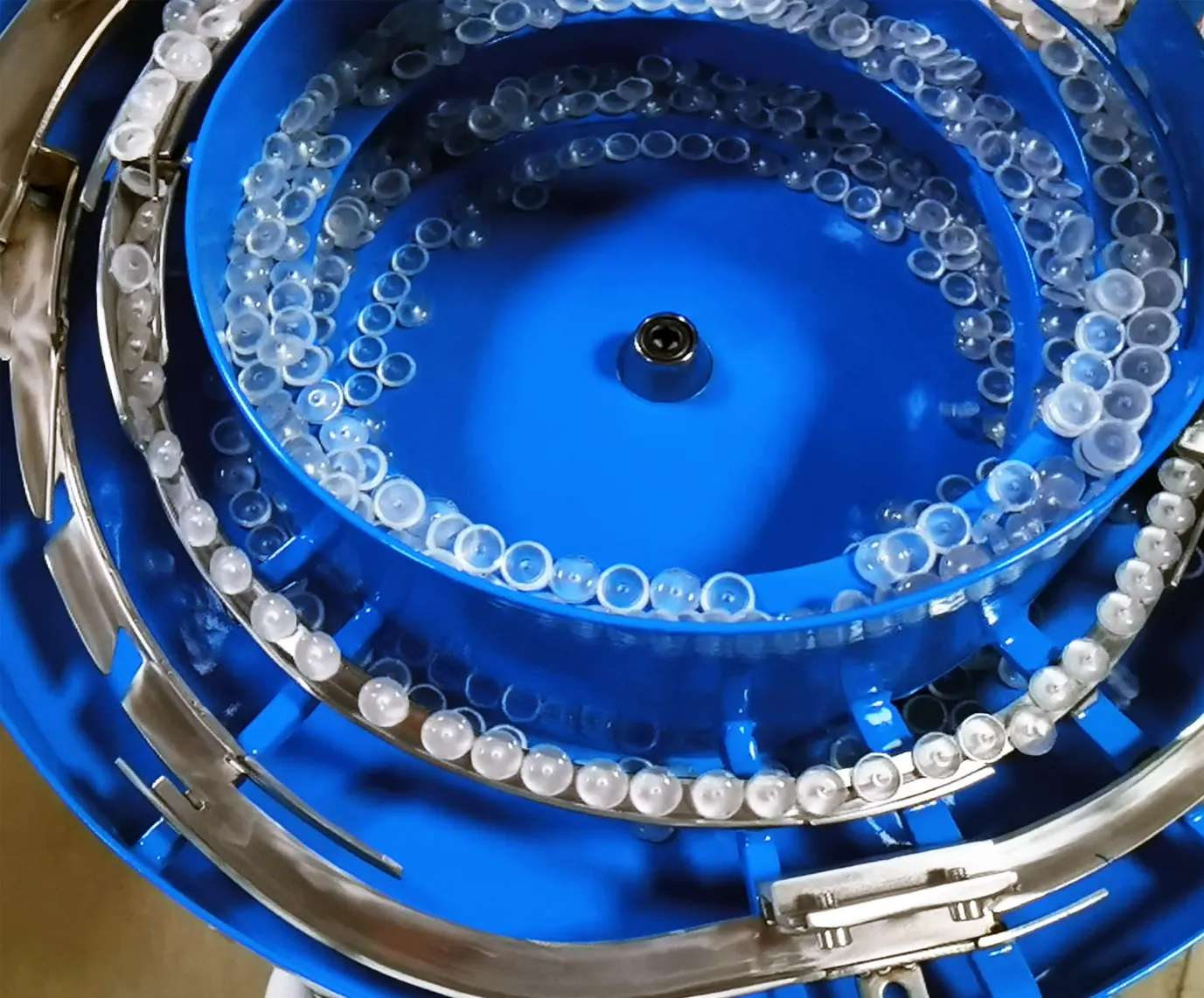
The architecture that removes the jam-versus-speed trade-off is two drives instead of one. The circular channel runs in the low-frequency band — this installation was tuned in the 50–60 Hz range — and its only job is to move lenses around the bowl and lift them onto the track; because it can be driven harder or softer without changing presentation, the bowl absorbs changes in load.
The linear channel runs at a higher frequency and holds the presentation geometry constant, so lens speed at the escapement stays the same whether the bowl is full or nearly empty. Custom routes and wheel spokes were engineered around the customer’s lens sizes, with track width and escapement set for the smallest part in the portfolio and verified upward.
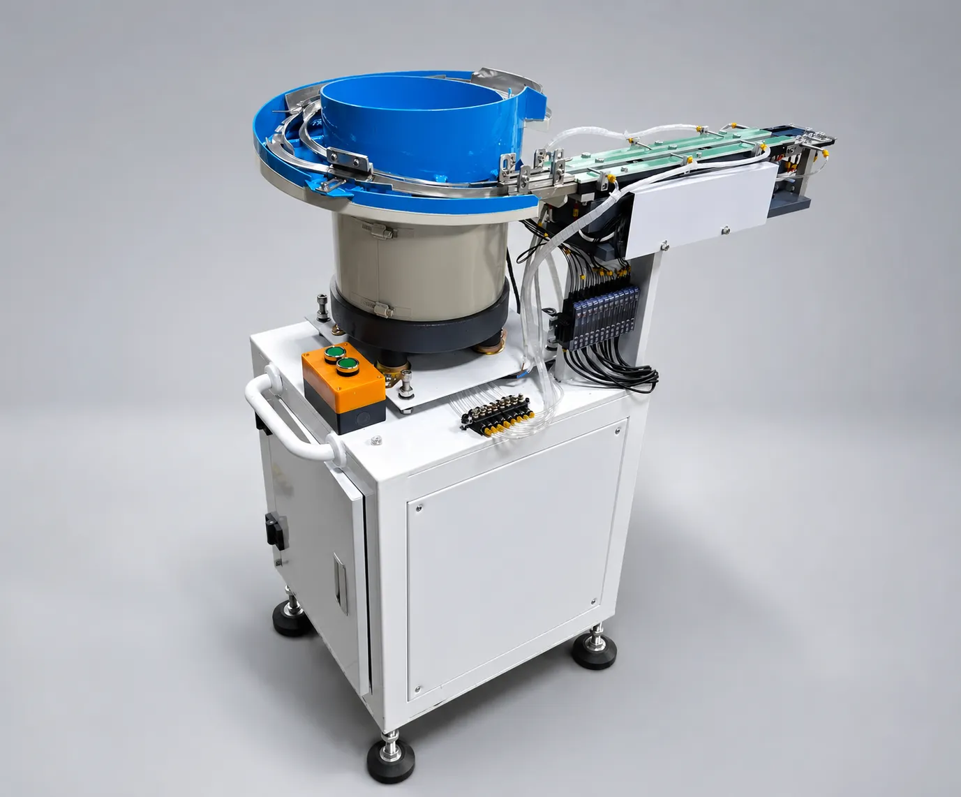
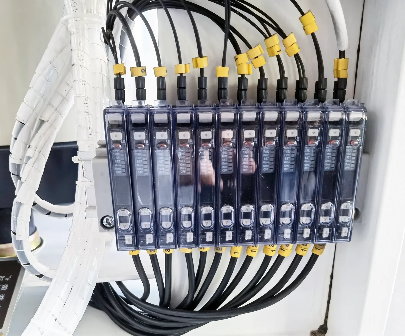
| Item | Model | Qty |
|---|---|---|
| Lens vibrating feeder (custom) | JHIMS DPS-2 platform | 1 |
| Pick-and-place integration | Samsung SLM120S (existing) | 1 |
From the published case record: a custom lens vibrating feeder engineered for the Samsung SLM120S line. JHIMS sales records also show 2 DPS-2 lens vibratory feeders delivered in March 2018.
| Feature | Details |
|---|---|
| Lens Diameter Range | 3mm – 25mm |
| Lens Types | Inner/outer three-feet, four-angle reflection lenses |
| Number of Tracks | 2 disc tracks standard, expandable to 10; 2 linear tracks |
| Transfer Speed | 0.5–1 second per lens (single channel) |
| Rejection Rate | Under 0.5% |
| Vibration Control | Dual-frequency vibration (50–60 Hz) |
| PLC & HMI | Mitsubishi FX5U + 7-inch Weintek HMI (50 profiles) |
| Power Supply | 220V AC, 50–60Hz, single phase, 0.55 KVA |
The equipment list is deliberately short because the value of the project is in the tooling and control work rather than in a long bill of materials. One custom lens vibrating feeder on the DPS-2 platform was integrated with the customer’s existing Samsung SLM120S placement machine; the published sales record shows two DPS-2 feeders delivered for this account in March 2018.
Because the feeder is a standalone unit with its own control cabinet, nothing in the placement machine had to be modified: the mounting bracket follows the head, the pick-up platform is set to the nozzle travel, and the lens recipe lives in the feeder PLC — so the installation stays reversible if the line is reconfigured later.
The three phases exist to make the outcome repeatable rather than to lengthen the project. Process analysis maps the failure modes — where lenses collide, where they rotate, where the operator used to intervene — and produces the tooling brief.
Custom engineering turns that brief into bowl geometry, wheel spokes, routes and controller settings, all proven against the customer’s own lenses rather than sample parts from stock. Installation then positions the feeder at the machine, connects the line interface and verifies presentation height with the production nozzle, after which the settings are stored as a profile so a later lens change is a recall rather than a re-tuning exercise.
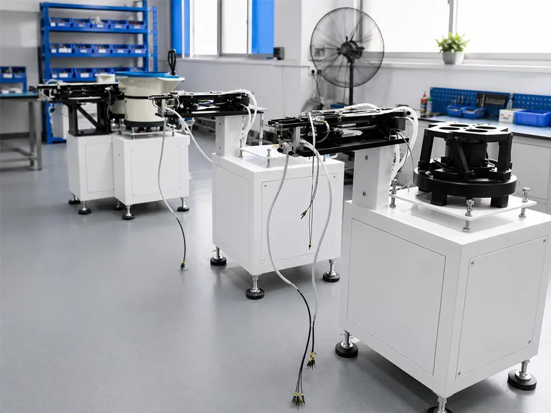
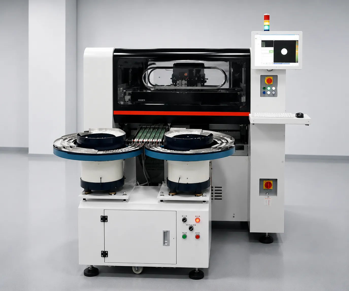
Watch the JHIMS lens vibrating feeder feed LED lenses to a pick-and-place machine. Watch the full feeder video on YouTube.
When watching the video, three things are worth looking at because they are what the project was actually about. First, the lenses in the bowl: they should circulate continuously with no queue forming at the track entrance, which is the visual signature of a feeder that is not fighting its own load.
Second, the lenses on the linear track should arrive at the escapement already oriented, so the nozzle meets a flat, centred lens rather than correcting an angled one. Third, the pick-up rhythm: a visible change in lens spacing between a full and a nearly empty bowl is the drift a single-frequency feeder shows and this installation removed.
Reported in the published JHIMS case record for the lens vibrating feeder:
The three published results are connected, and reading them together explains the payback. Eliminating jamming removes unplanned stops, which restores the machine’s available time; a 30% increase in feeding speed raises output without changing the placement programme.
The 15% cost reduction comes from removing an operator from the feeding task and reducing lens scrap caused by manual handling — including scratches and dropped parts that never appear in a jam count but do appear in the material cost. For a lighting line running several shifts the saving accumulates on both sides, which is why this kind of automation usually pays back in under a year.
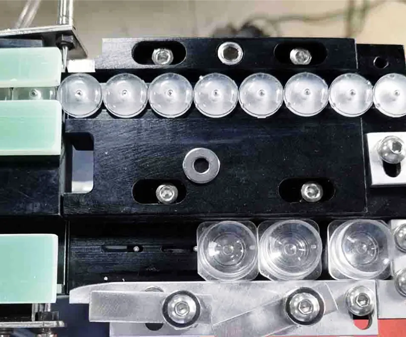
Acceptance in feeding projects is a measured event, not a promise, and the sequence is the same for every lens type we handle. The customer sends 500–800 lenses of each type; the tooling is built and the feeder runs for 48 hours with those parts.
The run produces a report with time-series amplitude and cycle data, a breakdown of rejection causes by category, microscope inspection of lens edges after feeding, and video of the run. Measured feed rate, orientation quality and rejection are recorded in the machine birth certificate, and a 120-point quality check covers assembly and electrical work before packing.
For this customer the same sequence applied, which is why the published results can be stated as project outcomes rather than sales claims: jam-free behavior, faster feeding and reduced cost were observed on the customer’s own lenses in their own product family.
If you are evaluating a similar project, ask for the burn-in report structure first — a supplier who cannot describe how they will prove performance on your lenses before shipping is a supplier whose performance will be debated after installation instead.
What is measured before a feeder of this class ships, and where each result is recorded.
| Item | How it is verified | Recorded in |
|---|---|---|
| Feed rate | Timed cycles per channel with the customer’s lenses | Burn-in report and machine birth certificate |
| Rejection rate | Counted rejects with cause categories over a 48-hour run | Burn-in report |
| Orientation quality | Microscope inspection of lens edges after feeding | Burn-in report |
| Jam-free operation | Unplanned stops attributable to feeding, logged across the run | Burn-in report |
| Lens sample quantity | 500–800 lenses per type supplied by the customer | Sample test record |
| Amplitude stability | Time-series amplitude data across the fill range | Burn-in report |
| Assembly quality | 120-point quality check before packing | QC record |
| Profile recall | Stored settings recalled and confirmed per lens type | Machine documentation |
FeaturedJHIMS DPS-2 Lens FeederMulti-channel lens vibratory feeder – 0.5–1s per lens, under 0.5% rejection, PLC profile recall.View product →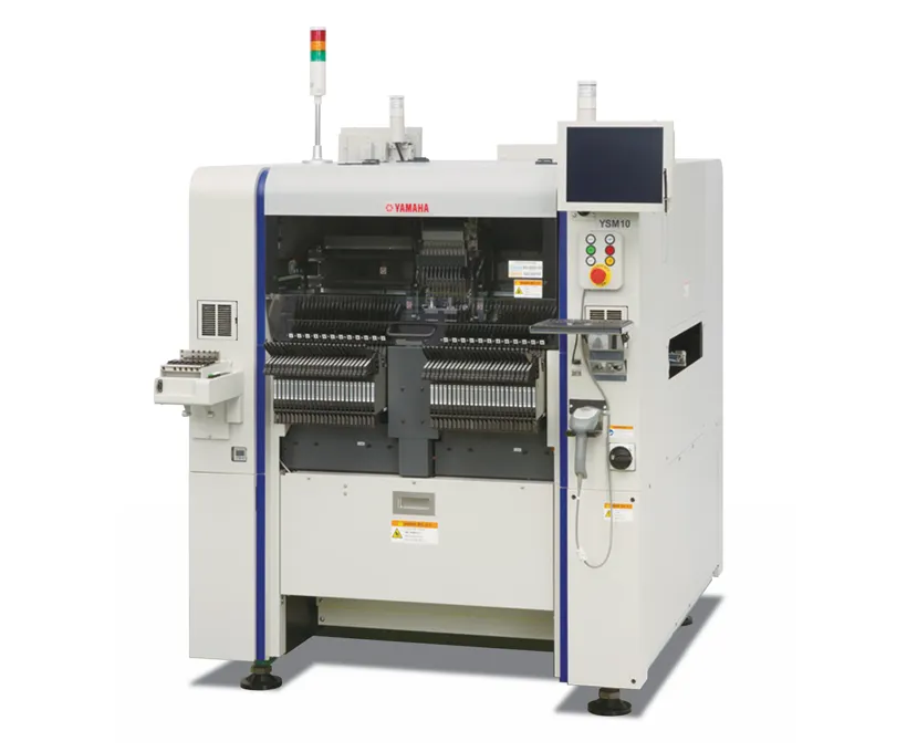 CompanionYamaha YSM10 MounterHigh-speed compact modular mounter – 46,000 CPH, 96 feeders, e-Vision + Side View.View product →
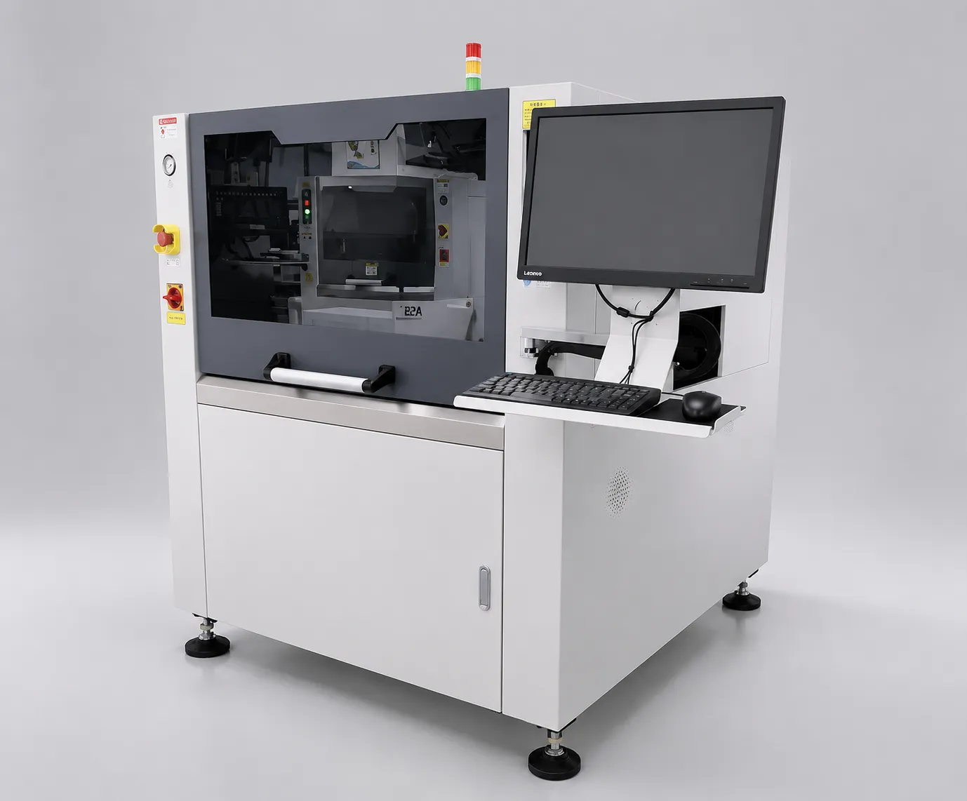 JHIMS L5 Solder Paste PrinterAutomatic SMT stencil printer – ±0.025mm accuracy with vision-aligned printing for the SMT line.View product →
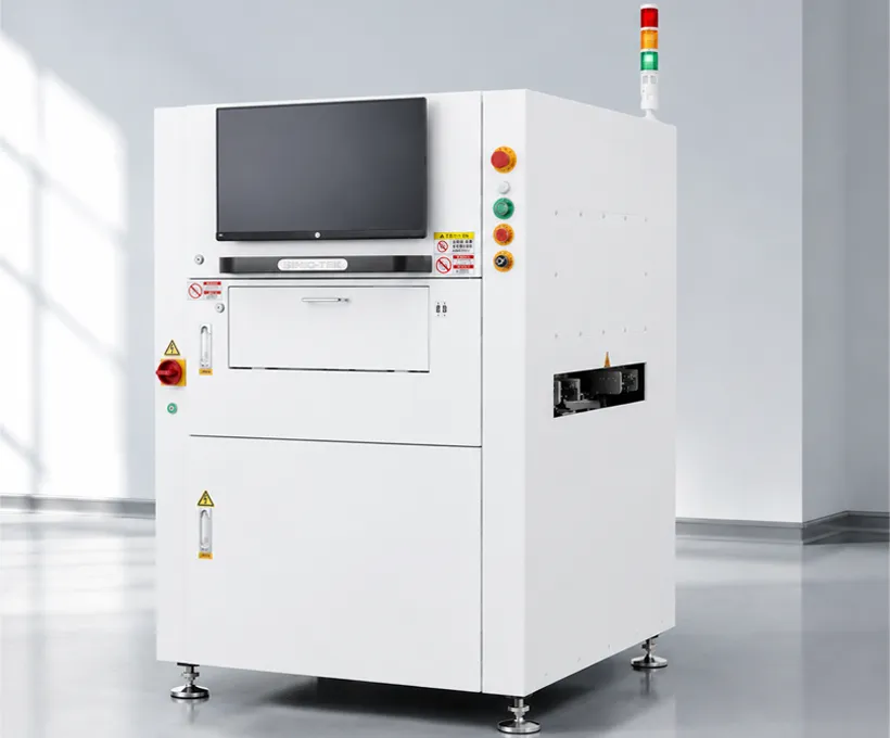 RelatedJHIMS S630 3D SPI3D solder paste inspection – verifies print quality before reflow.View product →
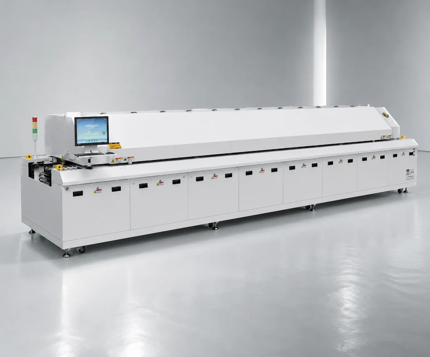 RelatedJHIMS R10 Reflow OvenLead-free hot-air reflow soldering for SMT lines – 20 heating zones, up to 300°C peak.View product →
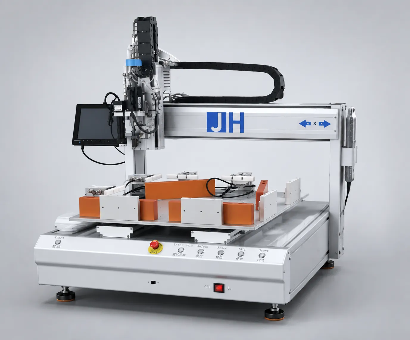 RelatedJHIMS ZM500 Screw MachineAutomated screw tightening and removal for electronics assembly.View product →DPS-2 Lens Vibratory Feeder FAQ40 real-world Q&As on the DPS-2: speed, channels, lenses, changeover and integration.Read article →DPS-2 Lens Vibratory Feeder OverviewHow the DPS-2 feeds optical lenses to pick-and-place machines reliably.Read article →
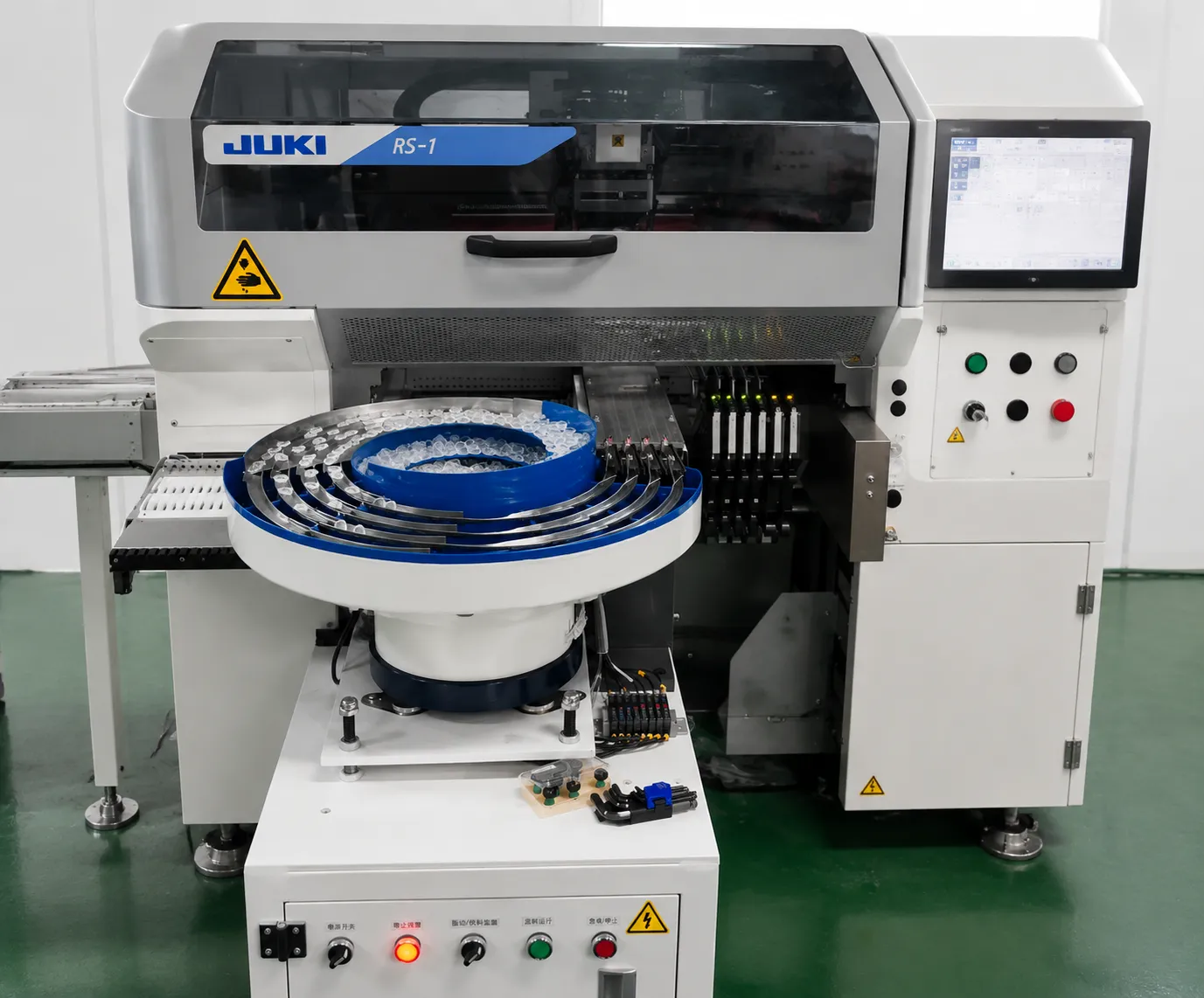 Manual vs Automatic SMT Lens FeedingCompare manual placement vs automatic lens feeding for high-mix production.Read article →
 Lens Feeder Case Study: LED Lighting RussiaLens vibrating feeder automating lens assembly for a Russian LED lighting manufacturer.Read article →
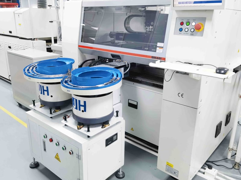 Lens Feeder Case Study: Hanwha SM481 DongguanCustom lens feeder for a Dongguan LED manufacturer on a Hanwha line.Read article →
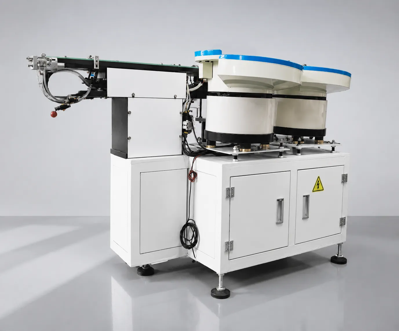 JHIMS Lens Feeder ROI AnalysisPayback analysis for automatic lens feeding vs manual placement.Read article →
Send your lens samples for a free 48-hour lens vibrating feeder test — we will validate throughput and jam rate on your line, and we reply within 12 working hours (Mon–Sat, 09:00–23:00 China Standard Time, UTC+8).