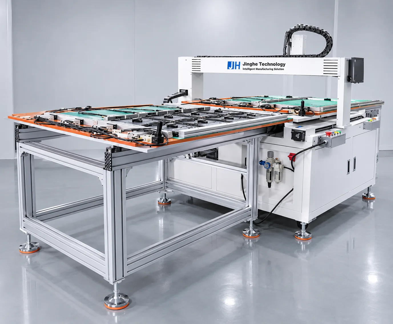
JHIMS BL18 — vertical 4-axis screw fastening machine for LED display cabinets
Video Guide
How to Operate the JHIMS BL18 Screw Fastening Machine: 19 Step-by-Step Video Tutorials
The complete operator course for the BL18 vertical four-axis LED cabinet screw fastening machine — 19 videos in the order they were filmed, from first power-on and coordinate teaching to nozzle replacement, camera calibration and maintenance. Built for the Argentina installation.
✎ Written by JHIMS Engineering📅 Updated 2026-11-08🎬 19 videos
Direct answer: Watch the 19 videos in the order below. Steps 1–3 get the machine powered, in your language and in its coordinate system; steps 4–8 teach the screw positions, the Z-axis height and the first test cabinet; steps 9–13 are the running-and-recovery set (workflow, screw feeder, nozzle adjustment and replacement); steps 14–19 are setup, camera calibration, torque parameters, dual-fixture programming and maintenance. Every step also appears as written text further down, and the fault table maps each symptom straight to the video that fixes it.
Key Takeaways
1 Steps 1–8 = first installation weekend. Do not skip step 5 (coordinates) — every later step depends on it.
2 A tilted screw is nearly always the nozzle (step 12), not the feeder. Check the nozzle before touching the tracking.
3 A stopped feeder is step 11: open the lid and look at the track before changing any parameter.
4 After any nozzle change or camera work, recalibrate (steps 13 and 15) or ±0.02mm repeatability is gone.
Before You Start
Four things must be true before Part 0 makes sense. Machine: AC 220 V, 50 Hz, main breaker on, air inlet connected at 0.55–0.65 MPa. Consumables: M4×10 screws with flat and spring washers — all identical. Cabinet: one LED module plus its frame, within the 1024×1024×105 mm fixture limit. Safety: you know where the emergency stop is, and no one reaches into the fixture while the machine is powered.
Have the pendant in front of you and the machine in manual mode. Every part below assumes you are standing at the machine, not reading in an office. The player counter numbers this list 1–19 and the YouTube titles are Part 0–18, so Step 1 is Part 0 — each step below shows both numbers.
The player and this list work together: pick any step and it plays in the window above without leaving the page. The list is in the order the videos were filmed, which is also the order of the procedure below.
BL18 Screw Fastening Machine — Written Step-by-Step Guide
The same 19 videos as text, grouped into the four phases an operator actually works through. Use this section at the machine when you do not want to scrub a video.
Phase 1 — Get it running (Steps 1–3 = Part 0–2)
Power and language — Switch the main breaker on, then use the pendant menu to set the interface to English (or 中文). Press reset to clear the alarm that appears after a language change — this is normal, not a fault.
Know the two fixtures — The machine fastens on one fixture while the other is loaded. Fixture 1 and Fixture 2 each carry their own coordinate set, so a cabinet type is a program, not a re-teach.
Understand the coordinate screen — X/Y/Z positions are written and confirmed on the pendant; the yellow cursor marks the parameter being edited. Nothing is saved until you confirm the coordinate.
Phase 2 — Teach the cabinet (Steps 4–8 = Part 3–7)
Clear the red default parameters — Factory defaults arrive marked in red and some servo options are missing. Delete the red set and restore the defaults before teaching anything.
Record every screw hole — Move the head to each screw hole on Fixture 1 and store the coordinate. This is the step that decides whether the rest of the program is right — one missed hole is one cabinet with a loose screw.
Set the Z-axis fastening height — Approach at medium speed, bring the bit to the hole centre, then set the height so the screw seats without the panel flexing (steps 6 and 7 do this twice — once as a setting, once as a single-step test).
Test on a real cabinet — Run the program on an LED module cabinet before production. Confirm every screw is seated and that the cabinet is clamped flat.
Phase 3 — Run and recover (Steps 9–13 = Part 8–12)
Learn the cycle — Fixture seated, module orientation checked, obstacles cleared, fasten, unload — the machine repeats this cycle, so anything that breaks it is either the program or the screw path.
Feeder stopped? Step 11 — Open the lid, look at the track for a jam, adjust the track height and restart. Do not change parameters before checking the track.
Screw blown in tilted? Step 12 — Lower the nozzle to adjust the position using Preview Trajectory, then check the cylinder actions against the indicator lights.
Worn nozzle? Step 13 — Replace the nozzle, raise it clear for safety, then re-align the camera red cursor before running.
Phase 4 — Setup, calibration and maintenance (Steps 14–19 = Part 13–18)
Remove interference before a job — Step 14 shows which parts must come off to avoid a collision — and where they go back.
Calibrate the camera — Step 15 is the full calibration; do it after any nozzle change, any camera work, or if screws start landing consistently off-centre.
Set torque and detection — Step 16 sets fastening torque, detection thresholds and safety parameters. Torque is a setting, not a feel — this is what makes every screw identical.
Program the second fixture — Step 17 switches left/right and gives each fixture its positions, which is what allows two different cabinets at once.
Pickup height and first driven screw — Step 18 sets pickup height so the screw is held properly, then drives one screw before automatic run.
Daily and weekly routine — Step 19 covers operation, finishing a partly assembled cabinet from a later position, and the lubrication and wipe-down that keeps the head accurate.
What each video covers
1. Machine overview and how to switch the interface language. Watch first if the teach pendant is not in your language: switching EN/中文, clearing the alarm with the reset key, and the menu layout you will use for every job.
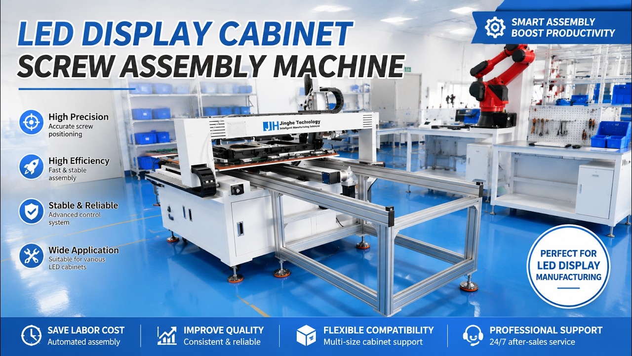
2. LED display cabinet assembly machine — screw fastening automation overview. What the machine does on a real cabinet, and how the two fixtures relate to one fastening head.
3. Power-on sequence, screen basics and coordinate system. Where the main switch is, what the start screen shows, and how the X/Y/Z coordinates are written and confirmed.
4. parameter defaults and servo configuration. What the red default parameters mean, why some servo options are missing, and how to restore the factory defaults.
5. Recording screw-hole coordinates on Fixture 1. Teaching the screw positions on the first fixture, one hole at a time, and confirming each stored coordinate.
6. Setting the Z-axis fastening height. How to bring the head down to the cabinet, set the fastening height at medium speed, and check the bit sits in the screw hole centre.
7. Z-axis height and single-step fastening test. The same height procedure repeated with the single-step test, plus the points to watch before you trust a program.
8. Screw assembly test on an LED module cabinet. Running the program on a real module cabinet to confirm every screw is seated before production.
9. How a full machine cycle works. The workflow cycle: Fixture 1 recognised by the machine, module orientation checked, obstacles cleared, fastening, unload.
10. Screw feeder and air supply system. The feeder, the air inlet and the branch that feeds the fastening head — what has to be connected before the first run.
11. Screw feeder jam fix. The single most common stoppage: open the lid, check the track, adjust the height, clear the jam and restart.
12. Nozzle adjustment when a screw is blown in tilted. Preview trajectory, bring the nozzle down, correct the position, and the cylinder actions to check with the indicator lights.
13. Nozzle replacement and camera cursor. Replacing a worn nozzle, lifting it clear, then aligning the camera red cursor so pickup lands in the right place.
14. Setup and safety checks. Removing the interfering parts before a job so the head cannot collide, and where each part has to go back.
15. Vision camera calibration. The full camera calibration: screen reflection check, then the distance calibration that keeps ±0.02mm repeatable.
16. Torque, detection and safety parameters. Setting fastening torque, the detection thresholds and the safety parameters, then confirming them on a test screw.
17. Programming a dual-fixture machine. Switching between left and right fixtures, the three fixture parameters, and how each fixture gets its own positions.
18. Pickup height and screw driving test. Setting the pickup height so the screw is held properly, then driving one screw and starting automatic run.
19. Operation and maintenance. Daily operation, finishing a partly completed cabinet from a later position, and the lubrication and wipe-down routine.
Troubleshooting & Fault Table
Symptoms in the order operators report them, with the video that fixes each one. The video number is the fastest thing to give our engineers if you need to call.
Symptom
Most likely cause
What to do
Video
Screw blown in tilted or not seated
Nozzle position or worn nozzle
Lower nozzle and correct position (Step 12); replace the nozzle if worn (Step 13)
12 / 13
Machine stops feeding screws
Jam in the feeder track or wrong track height
Open the lid, check the track, adjust height, restart (Step 11)
11
Screws consistently land off-centre
Camera needs calibration
Run the camera calibration (Step 15), then test one screw
What to check, how often, and where it is demonstrated. Most fastening-quality complaints trace back to one of these rows being skipped.
Interval
Task
Demonstrated in
Every shift
Check the feeder track and nozzle for screws or debris
Step 19
Every shift
Check the air supply is within 0.55–0.65MPa
Step 10
Weekly
Wipe down and lubricate the moving parts, clear used oil
Step 19
After any nozzle change
Re-align the camera cursor and recalibrate
Steps 13 / 15
After any camera or head work
Full camera calibration and one driven-screw test
Steps 15 / 18
When fastening quality drifts
Re-check torque and detection parameters
Step 16
Daily checklist before the first cabinet
Air pressure within 0.55–0.65MPa
Feeder track clear, no screws sitting sideways
Nozzle straight and undamaged
Correct program recalled for the cabinet type
Fixture clamped, cabinet sitting flat
Parameters Quick Reference
The settings the videos refer to, in one place, so you do not have to scrub back through a step to confirm a value.
Item
Value
Screw specification
M4×10 with flat & spring washers
Fastening axes
3 fastening axes + 1 feed axis
Positioning accuracy
±0.02mm
Alignment
Camera-assisted, calibrated per Step 15
Max. fixture
1024×1024×105mm
Program storage
1,000 programs
Power
AC 220V, 50Hz
Operating air pressure
0.55–0.65MPa
Reported pace (this installation)
About 2.5 seconds per screw
Frequently Asked Questions
How long does it take to learn the machine?▼
An operator who has never seen it can normally power up, teach a cabinet and run a test in one working day using Steps 1–8. Steps 9–19 are the recovery, calibration and maintenance set — learn them before you need them.
In what order should I watch the videos?▼
In the numbered order on this page, which is the order they were filmed. Steps 1–8 build one cabinet program end to end; skipping ahead leaves you without the coordinates later steps depend on.
Is there a written procedure, or only video?▼
Both. Every video has a written phase section further down this page, plus a fault table that maps each symptom to the video that fixes it.
The pendant is in Chinese — how do I change it?▼
Step 1 shows the menu path: go to the last menu page, open Other, then the first option, and enter 2 for English or 1 for Chinese. Press reset afterwards to clear the alarm.
Why does an alarm appear after I change the language?▼
That is expected behaviour, not a fault. Press the reset key and the alarm clears.
What is the first thing to check when a screw is not seated?▼
The nozzle. A tilted or unseated screw is almost always nozzle position or a worn nozzle — Step 12 for adjustment, Step 13 for replacement. Check that before touching the feeder or the program.
The machine stopped feeding screws. What now?▼
Step 11. Open the feeder lid, look at the track for a jam or a screw sitting sideways, adjust the track height, then restart. Do not change parameters until the track is confirmed clear.
How often do I need to calibrate the camera?▼
After any nozzle change, any camera or head work, and whenever screws start landing consistently off-centre. Step 15 is the full procedure; Step 13 aligns the cursor after a nozzle change.
How do I set the torque?▼
Torque is a parameter on the pendant, not a mechanical adjustment — Step 16 covers torque, detection thresholds and safety parameters together.
Can I run two different cabinets at the same time?▼
Yes. The left and right fixtures are independent, so each can hold a different cabinet with its own positions. Step 17 shows the fixture switch and the three fixture parameters.
How do I set the Z-axis height?▼
Approach at medium speed, bring the bit to the centre of a screw hole, then set the height. Steps 6 and 7 demonstrate it twice — once as a setting and once as a single-step test.
What pickup height should I use?▼
Step 18 sets pickup height so the screw is held reliably, then drives one screw to confirm before automatic run.
What do I do with a partly finished cabinet?▼
Continue it from a later position rather than restarting the program — Step 19 demonstrates the procedure.
What maintenance is required each week?▼
Feeder track and nozzle check every shift, air pressure confirmed every shift, wipe-down and lubrication weekly, and a calibration check after any nozzle or camera work. The full table is on this page.
What air pressure does the machine need?▼
0.55–0.65MPa. The air inlet and its branch to the fastening head are shown in Step 10 — check this before blaming the feeder.
What screw does this machine run?▼
M4×10 with flat and spring washers in the standard configuration. The machine is built to the customer’s screw specification, so a different size is agreed at order time.
How fast is it per screw?▼
About 2.5 seconds per screw as reported by the customer on this installation — roughly 1,440 screws per hour on a single fastening head.
Do the videos have subtitles I can follow?▼
Yes. Every tutorial has an English subtitle track, and the written phase summary on this page covers the same steps in text.
Who do I contact if the video does not solve it?▼
Contact JHIMS engineering with the video number and what the machine is doing. Mentioning the step number tells our engineers exactly which procedure you were in.
Does this guide apply to the ZM320 desktop machine?▼
Partly. The coordinate teaching and camera logic are similar, but the ZM320 has its own work area and single fixture, so use its own guide for machine-specific steps.
Fifty-three specific faults — tilted screws, feeder jams, torque alarms, sensor faults — are answered with an exact video minute on the BL18 troubleshooting FAQ.
Tell us the video number and what the machine is doing — JHIMS engineering replies within 12 working hours (Mon–Sat, 09:00–23:00 China Standard Time, UTC+8).

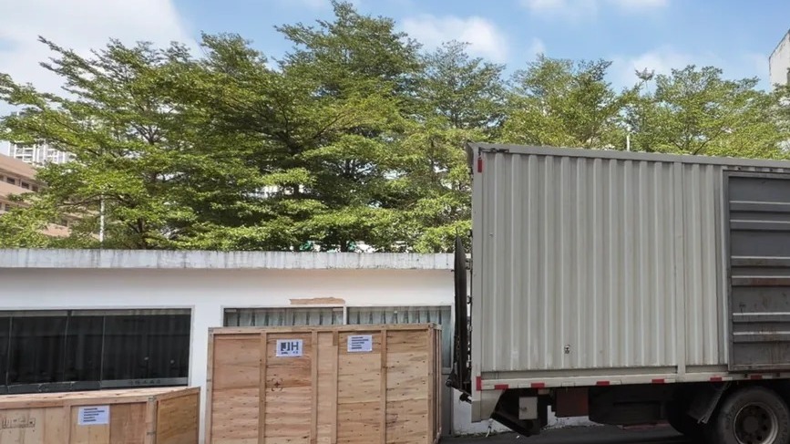 Case StudyArgentina Case StudyThe installation these videos were made for — pace, evidence and delivery records.Open →
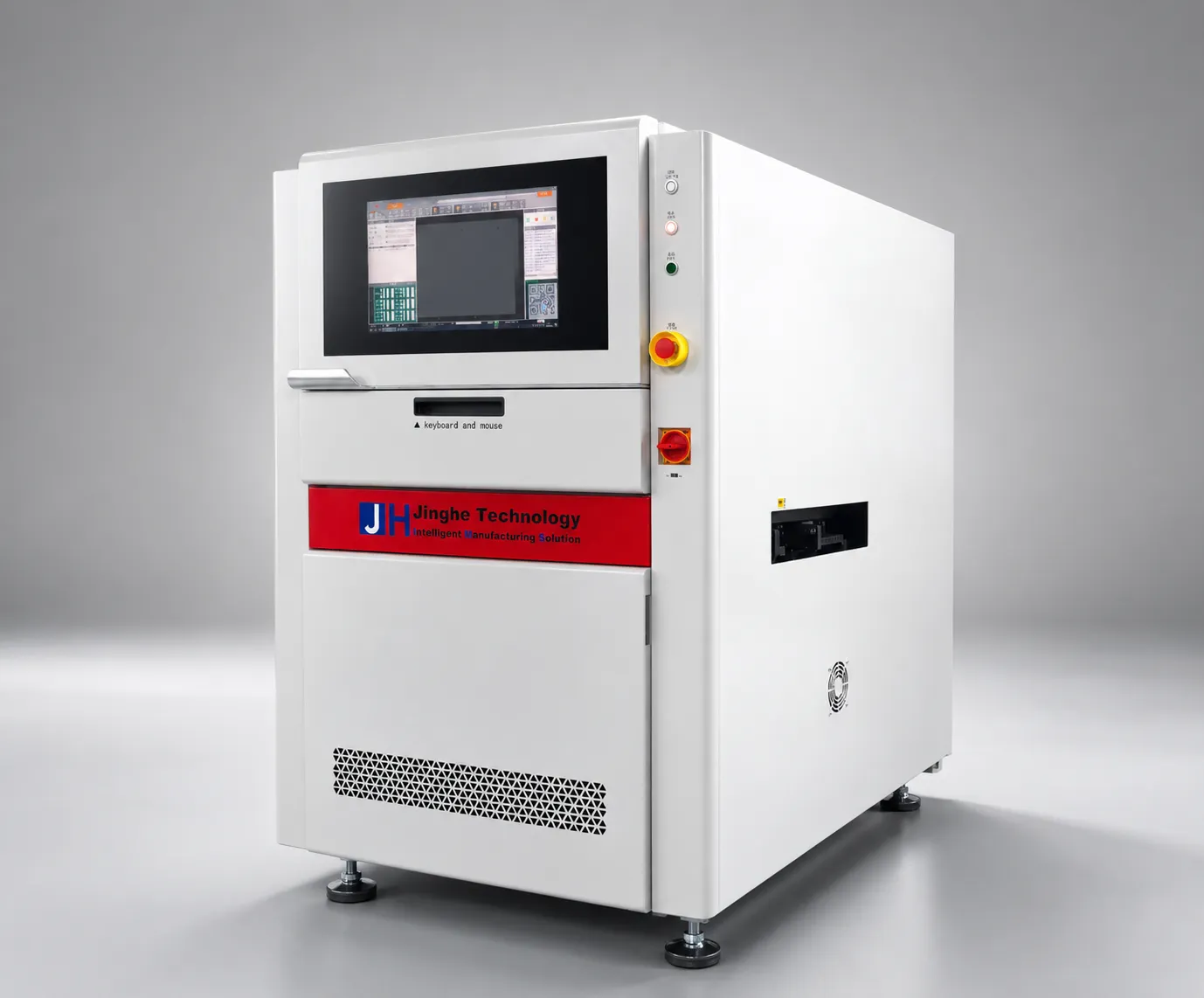 Other GuideR6-U Video GuideThe same 19-step video format applied to the R6-U UV laser marking machine.Open →
 SupportTechnical SupportRemote diagnostics, spare parts and service requests for JHIMS machines.Open →